


829172-00(0) © 2006 Ingersoll-Rand Company Limited
611 and 711 Series Swing Clear Continuous Hinges
Mark frame hole locations.
1
Mount hinge to door.
2
Mount door to frame
3
Check for proper operation.
4
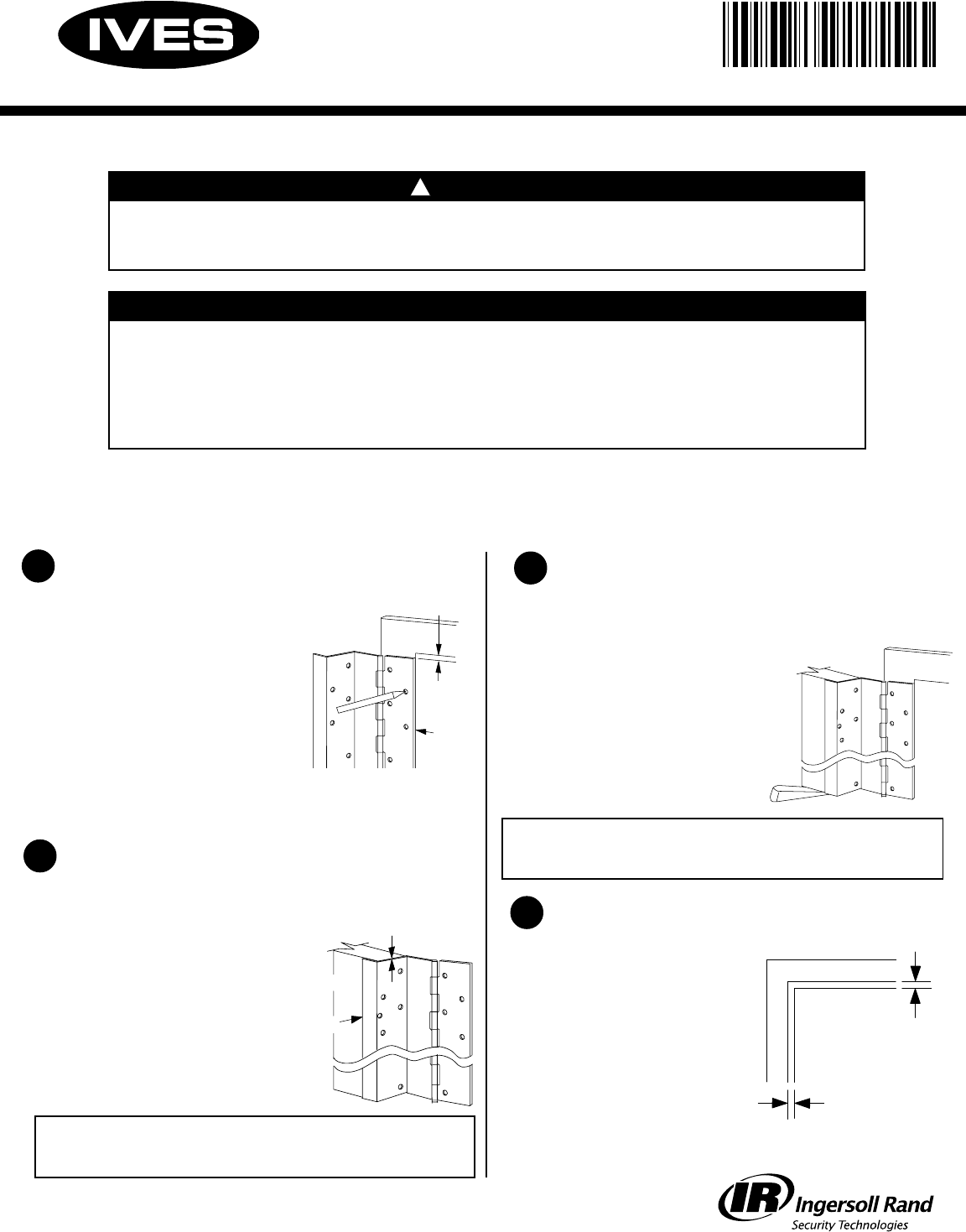
Determine TOP of hinge using
door and frame as guide.
Open hinge and place frame leaf
flat against surface of frame leaving
1/8 gap between top of hinge and
bottom of frame header, and edge
of hinge frame leaf flush with inside
edge of frame.
Mark hole locations on frame using
center punch. A center punch mark is
required to start self drilling screws accurately.
DO NOT install hinge to frame at this time.
Place door leaf of hinge against hinge
edge of door so that top of hinge is
flush with top of door and edge guard
is flush with inside face of door.
With hinge held firmly in place, use
#10 x 1/2 self drilling screws to fasten
leaf to metal door, or #10 x 1 wood
screws to fasten leaf to wood door.
Note: Fasten top screw first, and
bottom most screw second, making
sure hinge is aligned correctly.
ALL HOLE LOCATIONS ON HINGE LEAF MUST BE FASTENED TO
DOOR FOR PROPER OPERATION. FAILURE TO INSTALL ALL
FASTENERS WILL VOID WARRANTY AND UL FIRE LABEL LISTINGS.
Installation Instructions
Note: Before proceeding, check to be sure that hinge is proper size. Height of hinge should be 7/8
LESS than opening height. See other side of page for cutting instructions.
A.
B.
C.
A.
B.
1/8
Flush
Move door into opening and align
mounting holes in frame leaf of hinge
with marks on frame made in step 1
above. Note: An angle block, jack or
shims will be helpful in positioning
the door properly.
With hinge and door held firmly and
accurately in place, use #10 x 1/2
self drilling screws to fasten
frame leaf of hinge to frame
in marked locations.
A.
B.
ALL HOLE LOCATIONS ON HINGE LEAF MUST BE FASTENED TO
FRAME FOR PROPER OPERATION. FAILURE TO INSTALL ALL
FASTENERS WILL VOID WARRANTY AND UL FIRE LABEL LISTINGS.
Close door and check for
proper operation and
clearances. There should be
1/8 clearance between the
top of the door and the bottom
of the frame header, and 5/32
clearance between the frame
and edge of the door when the
door is closed. Adjustments
can be made by shimming
frame or door leaf of hinge.
A.
5/32
1/8
Door
Frame
Flush with
top of door
D
oor
Flush
829172-00
To bottom of frame
!
CAUTION
Please follow the installation instructions carefully. Not doing so may
result in improper installation and void the manufacturers guarantee.
INSTALLATION NOTES
No reinforcing is necessary except on heavy doors. Reinforcement and
rivet nuts are required in the frame and door when door weight exceeds
300 pounds. Maximum door weight is 600 pounds.
If the mullion is between the doors, treat as a single door installation. If
the mullion is behind the doors, treat as a double door installation.
Reinforcing and Rivet Nuts:
Pairs of Doors with Mullions: