


24
SERVICE AND ADJUSTMENTS
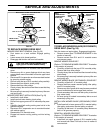
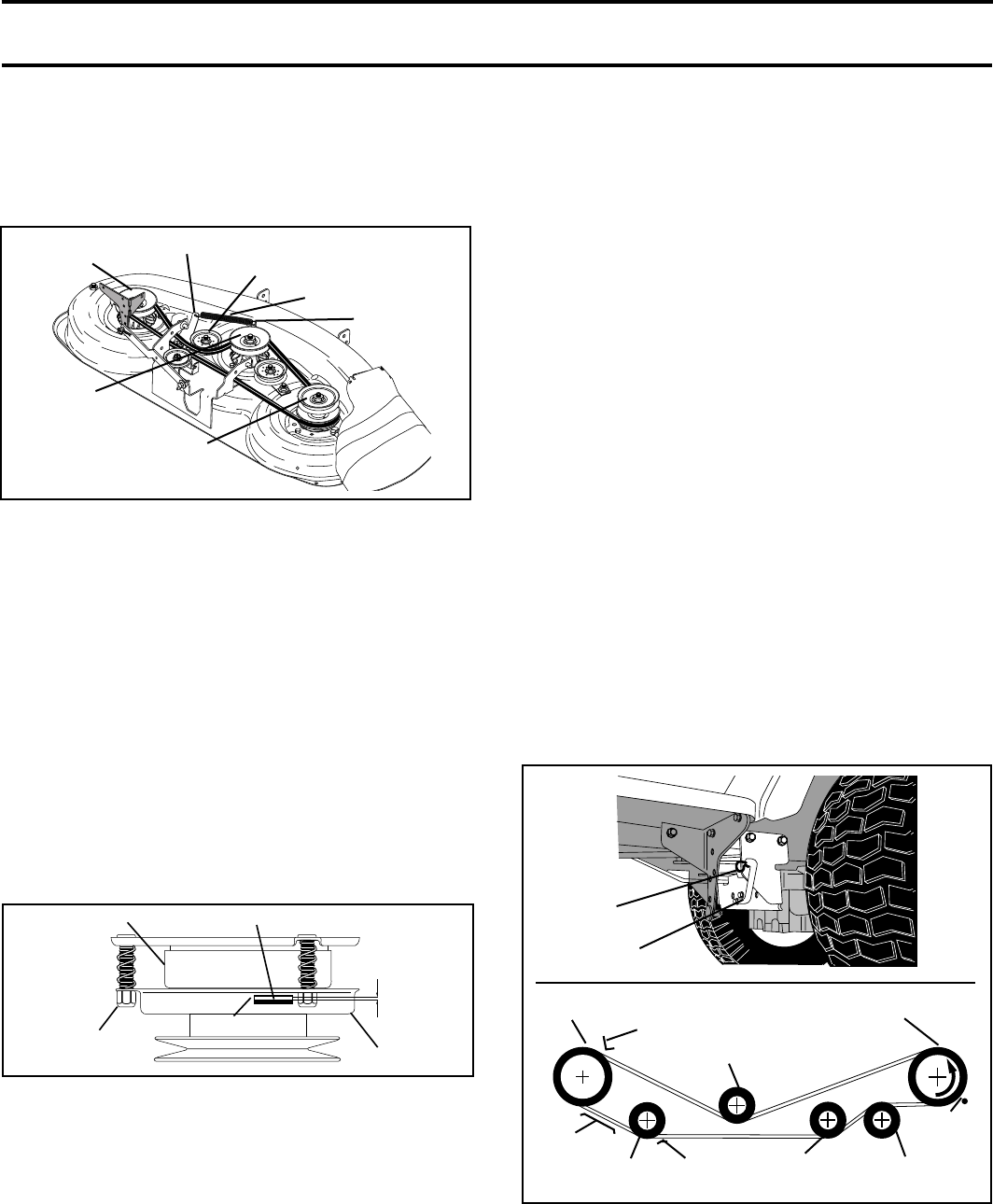
FIG. 26
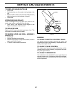
TO REPLACE MOTION DRIVE BELT
(See Fig. 26)
Park the tractor on level surface. Engage parking brake.
For ease of service there is a belt installation guide decal
on bottom of left footrest.
• Remove mower (See “TO REMOVE MOWER” in this
section of this manual.)
BELT REMOVAL -
• Create slack in belt by removing retainer spring from
drive belt tension handle.
• Remove belt from all idler pulleys, transaxle pulley and
then from engine pulley.
BELT INSTALLATION -
• Install new belt around engine pulley fi rst, then around
transaxle pulley and lastly into all the idler pulleys.
• Check to be sure belt is positioned correctly and is on
proper side of all belt keepers.
• Engage the drive belt tension handle and replace the
retainer spring.
• Reinstall mower.
2498
ENGINE PULLEY
02504
RETAINER
SPRING
DRIVE BELT
TENSION HANDLE
BELT KEEPER
BELT
KEEPER
V-IDLER
CLUTCHING
IDLER
CLUTCHING
FLAT IDLER
BELT
KEEPER
FLAT IDLER
TRANSAXLE
PULLEY
BELT
KEEPER
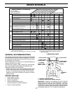
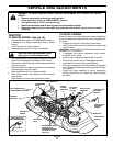
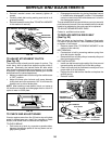
TO ADJUST ATTACHMENT CLUTCH
(See Fig. 25)
The electric clutch should provide years of service. The
clutch has a built-in brake that stops the pulley within 5
seconds. Eventually, the internal brake will wear which
may cause the mower blades to not engage, or, to not stop
as required. Adjustments should be made by your near est
authorized service center/department.
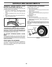
• Make sure attachment clutch and ignition switches are
in “OFF” position.
• Adjust the three nylon locknuts until space between
clutch plate and rotor measures .012" at all three slot
locations cut in side of brake plate.
NOTE: After installing a new electric clutch, run tractor at
full throttle and engage and disengage electric clutch 10
cycles to wear in clutch plate.
NYLON
LOCKNUT (3)
FIG. 25
00751
ROTOR
CLUTCH PLATE
.012"
SLOT (3)
BRAKE PLATE
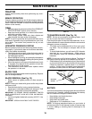
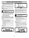
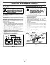
L.H. MANDREL
0251
5
CENTER
MANDREL
IDLER PULLEY
R.H. MAN DREL
COVER
SPRING
SEC OND ARY IDLER ARM
SEC OND ARY
SPRING ARM
• Reinstall mandrel covers and se cure ly tighten all
screws.
• Carefully check belt routing making sure belt is in all
grooves correctly.
• Reinstall mower to tractor (See “TO INSTALL MOWER”
in this section of manual).
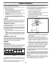
FIG. 24
TO CHECK AND ADJUST BRAKE
If tractor requires more than fi ve (5) feet to stop at highest
speed in high est gear on a level, dry concrete or paved
surface, then brake must be checked and ad just ed.
TO CHECK BRAKE
• Park tractor on a level, dry concrete or paved surface,
depress clutch/brake pedal all the way down and en-
gage parking brake.
• Disengage transmission by placing freewheel control
in “transmission disengaged” position. Pull freewheel
con trol out and into the slot and release so it is held in
the disengaged position.
The rear wheels must lock and skid when you try to manually
push the tractor forward. If the rear wheels rotate, the brake
needs to be adjusted or the pads need to be replaced.
TO ADJUST BRAKE/REPLACE PADS
Contact a qualifi ed service center.