


21
SERVICE AND ADJUSTMENTS
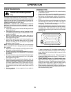
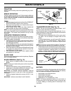
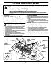
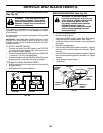
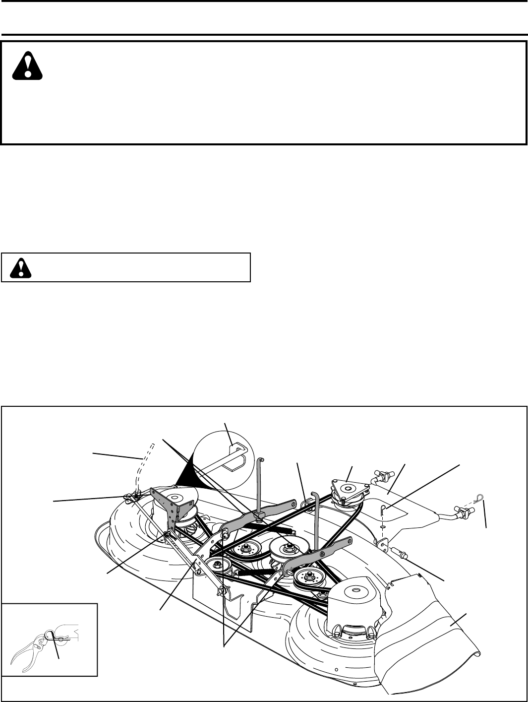
FIG. 18
WARNING: TO AVOID SERIOUS INJURY, BEFORE PERFORMING ANY SER VICE OR AD JUST -
MENTS:
• Depress brake pedal fully and set parking brake.
• Place attachment clutch in “DISENGAGED” position.
• Turn ignition key to “STOP” and remove key.
• Make sure the blades and all moving parts have completely stopped.
• Disconnect spark plug wire from spark plug and place wire where it cannot come in contact
with plug.
TO REMOVE MOWER (See Fig. 18)
• Place attachment clutch in “DIS EN GAGED” position.
• If equipped, turn height adjustment knob to low est
set ting.
• Lower mower to its lowest position.
• Disengage belt tension rod from lock bracket.
CAUTION: Rod is spring loaded. Have a
tight grip on rod and release slowly.
• Remove retainer spring holding anti-swaybar to chas sis
bracket and dis en gage anti-swaybar from bracket.
• Remove four retainer springs from front plate assembly
and remove plate.
• Remove retainer springs from sus pen sion arms at deck
and dis en gage arms from deck.
• Raise attachment lift to its highest position.
• Slide mower forward and remove belt from electric
clutch pulley.
• Slide mower out from under right side of tractor.
02565
SUSPENSION
ARMS
RETAINER
SPRING
ANTI-SWAY
BAR
SUSPENSION ARMS
DOUBLE LOOP
RETAINER SPRINGS
(Out ward pointing
deck pins)
CHASSIS
BRACK ET
SINGLE LOOP
RETAINER
SPRING
FRONT
MOWER
BRACKET
FLANGED PIN
ELECTRIC
CLUTCH
PULLEY
FRONT PLATE
AS SEM BLY
BELT TEN SION ROD
(DISENGAGED POSITION)
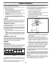
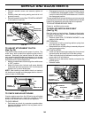
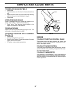
TO INSTALL MOWER
Be sure tractor is on level surface and mower suspension
arms are raised with attachment lift control. Engage park-
ing brake.
• Swing anti-sway bar to left side of mower deck.
• Slide mower under tractor with defl ector shield to right
side of tractor.
IMPORTANT: CHECK BELT FOR PROPER ROUTING IN ALL
MOWER PULLEY GROOVES.
• If equipped, turn height ad just ment knob coun ter -
clock wise until it stops.
• Lower mower linkage with attachment lift control.
• Be sure belt tension rod is in dis en gaged position.
• Install belt into electric clutch pulley groove.
• Place the suspension arms on outward pointing deck
pins. Retain with double loop re tain er spring with loops
up as shown.
• Install front plate assembly to tractor suspension
brack ets and retain with single loop retainer springs
as shown.
DOUBLE LOOP
RETAINER
SPRING
DEFLECTOR
SHIELD
LOCK BRACK ET
USE PLIERS FOR
RETAINER SPRINGS
LOOP UP
TRACTOR