


5
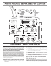
ASSEMBLY / PRE-OPERATION
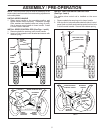
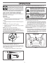
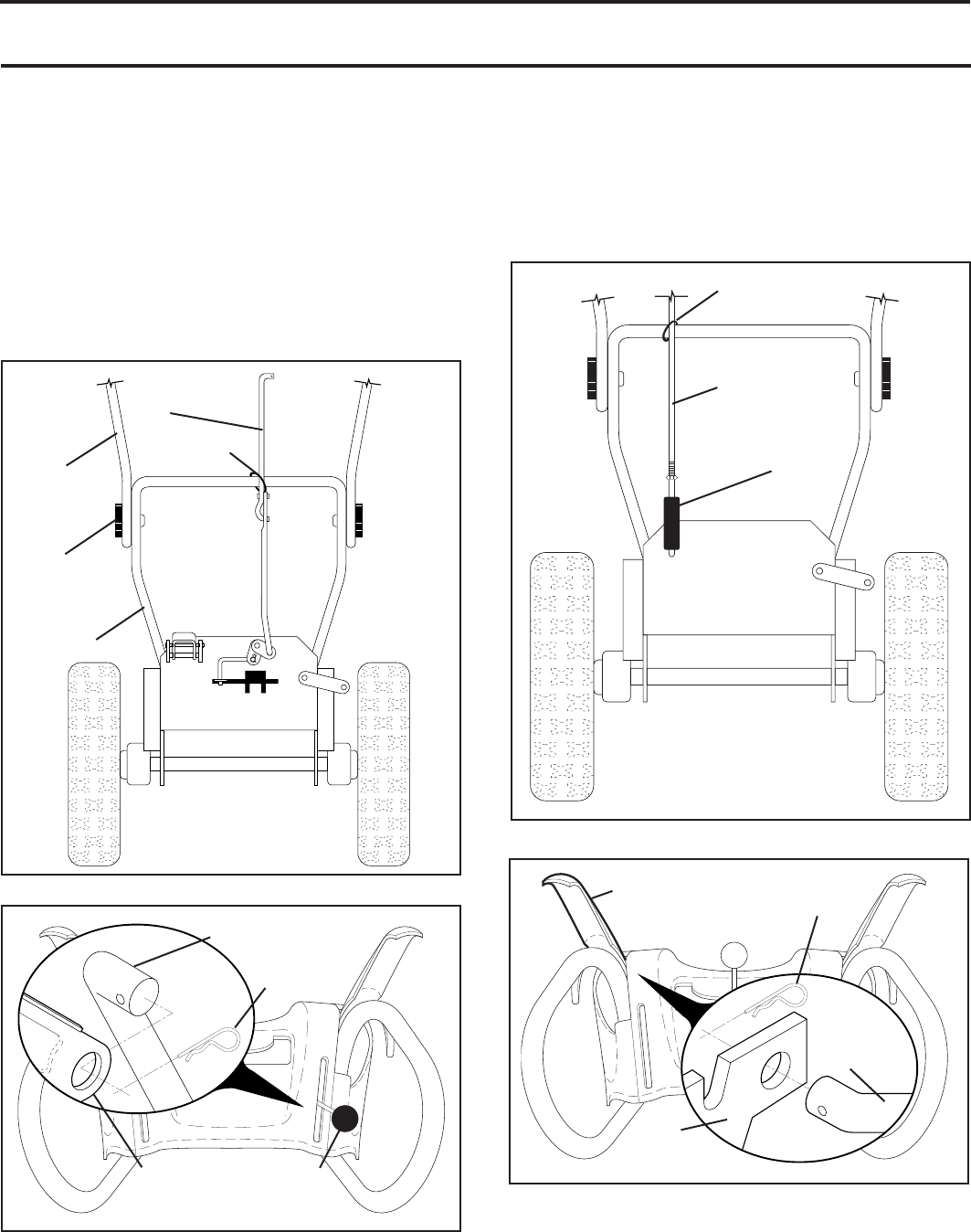
SPEED
CONTROL
ROD
HANDLE
KNOB
LOWER
HANDLE
PLASTIC TIE
UPPER
HANDLE
FIG. 1
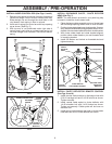
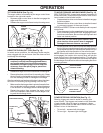
SPEED CON TROL ROD
SPEED
CONTROL
BRACKET
RETAINER
SPRING
SPEED
CONTROL
LEVER
FIG. 2
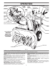
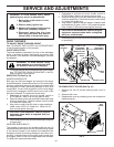
NOTE: The multi-wrench may be used for assembly of the
chute rotator head to snow thrower and making ad just ments
to the skid plates.
UNFOLD UPPER HANDLE
1. Raise upper handle to the operating position and
tight en handle knobs securely. Additional carriage
bolts, washers and handle knobs are in bag of parts.
Use to secure upper handle to lower handle. Install
in lower holes in handles.
INSTALL SPEED CONTROL ROD (See Figs. 1 and 2)
1. Remove plastic tie securing rod to lower handle.
2. Insert rod into speed control bracket and secure with
retainer spring.
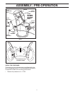
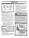
INSTALL TRACTION DRIVE CONTROL ROD
(See Figs. 3 and 4)
The traction drive control rod is installed on the snow
thrower.
1. Remove plastic tie securing rod to lower handle.
2. With top end of rod positioned under left side of control
panel, push rod down and insert top end of rod into hole
in drive control bracket. Secure with retainer spring.
TRACTION
DRIVE
CON TROL
ROD
DRIVE
CONTROL
BRACKET
RETAINER
SPRING
TRACTION DRIVE
CON TROL LEVER
FIG. 4
TRACTION DRIVE
CONTROL ROD
VINYL
SLEEVE
FIG. 3
PLASTIC TIE