


11
OPERATION
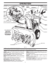
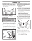
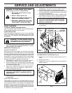
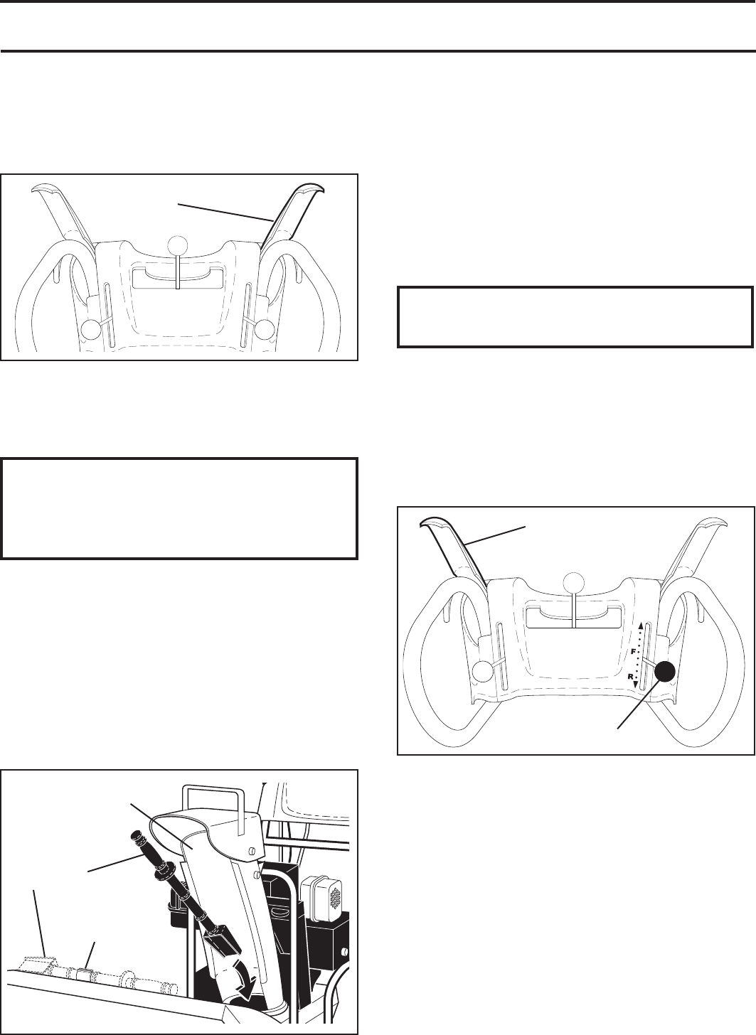
TO THROW SNOW (See Fig. 14)
The auger rotation is controlled by the auger control lever
located on the right side handle.
• Squeeze auger control lever to handle to engage the
auger and throw snow.
• Release the auger control lever to stop throwing snow.
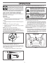
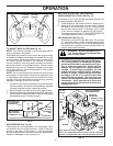
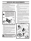
USING THE CLEAN-OUT TOOL (See Fig. 15)
In certain snow conditions, the discharge chute may be-
come clogged with ice and snow. Use the clean-out tool
to dislodge this blockage.
When cleaning, repairing, or in spect ing, make
certain all controls are disengaged and the au-
ger/impeller and all moving parts have stopped.
Disconnect the spark plug wire and keep the
wire away from the spark plug to prevent ac-
cidental starting.
• Release the auger control lever and shut off the engine.
• Remove the clean-out tool from it's mounting clip. Grasp
the tool firmly by the handle and push and twist the tool
into the discharge chute to dislodge the blockage.
After the packed snow has been dislodged, return the clean-
out tool to it's mounting clip by pushing it into the clip.
• Make sure the discharge chute is pointed in a safe direc-
tion (no vehicles, buildings, people, or other objects are
in the direction of discharge) before restarting engine.
• Restart the engine, then squeeze the auger control
lever to the handle to clear snow from the auger hous-
ing and the discharge chute.
AUGER
CONTROL
LEVER
FIG. 14
CLEAN-OUT
TOOL
FIG. 15
MOUNTING
CLIP
DISCHARGE CHUTE
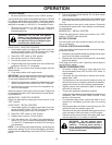
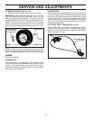
TO MOVE FORWARD AND BACKWARD (See Fig. 16)
SELF-PROPELLING, forward and reverse movement of
the snow thrower, is controlled by the traction drive control
lever located on the left side handle.
• Squeeze traction drive control lever to handle to en gage
the drive system.
• Release traction drive control lever to stop the forward
or reverse movement of the snow thrower.
SPEED and DIRECTION are controlled by the drive speed
control lever.
• Press downward on the speed control lever and move
lever to de sired po si tion BE FORE engaging the trac-
tion drive control lever. Be sure lever springs back and
locks into desired position.
CAUTION: Do not move speed con trol le ver
when traction drive control lever is en gaged.
Damage to the snow thrower can result.
• Slower speeds are for heavier snow and faster speeds
are for light snow and transporting the snow thrower. It
is recommended that you use a slower speed until you
are familiar with the operation of the snow thrower.
NOTE: When both traction drive and auger control levers
are engaged, the traction drive control lever will lock the
auger control lever in the engaged position. This will allow
you to release your right hand from the handle and adjust
the discharge chute direction without interrupting the snow
throwing process.
DRIVE SPEED
CONTROL LEVER
TRACTION DRIVE
CONTROL LEVER
FIG. 16
POWER STEERING OPERATION (See Fig. 17)
Steering triggers are used to assist in steering your
snow thrower. The triggers are located on the underside
of each handle. When a trigger is squeezed, it disen-
gages the drive wheel on that side of snow thrower and
allows it to turn in that direction.
• To turn left – squeeze left side trigger.
• To turn right – squeeze right side trigger.