


6
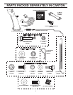
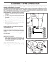
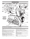
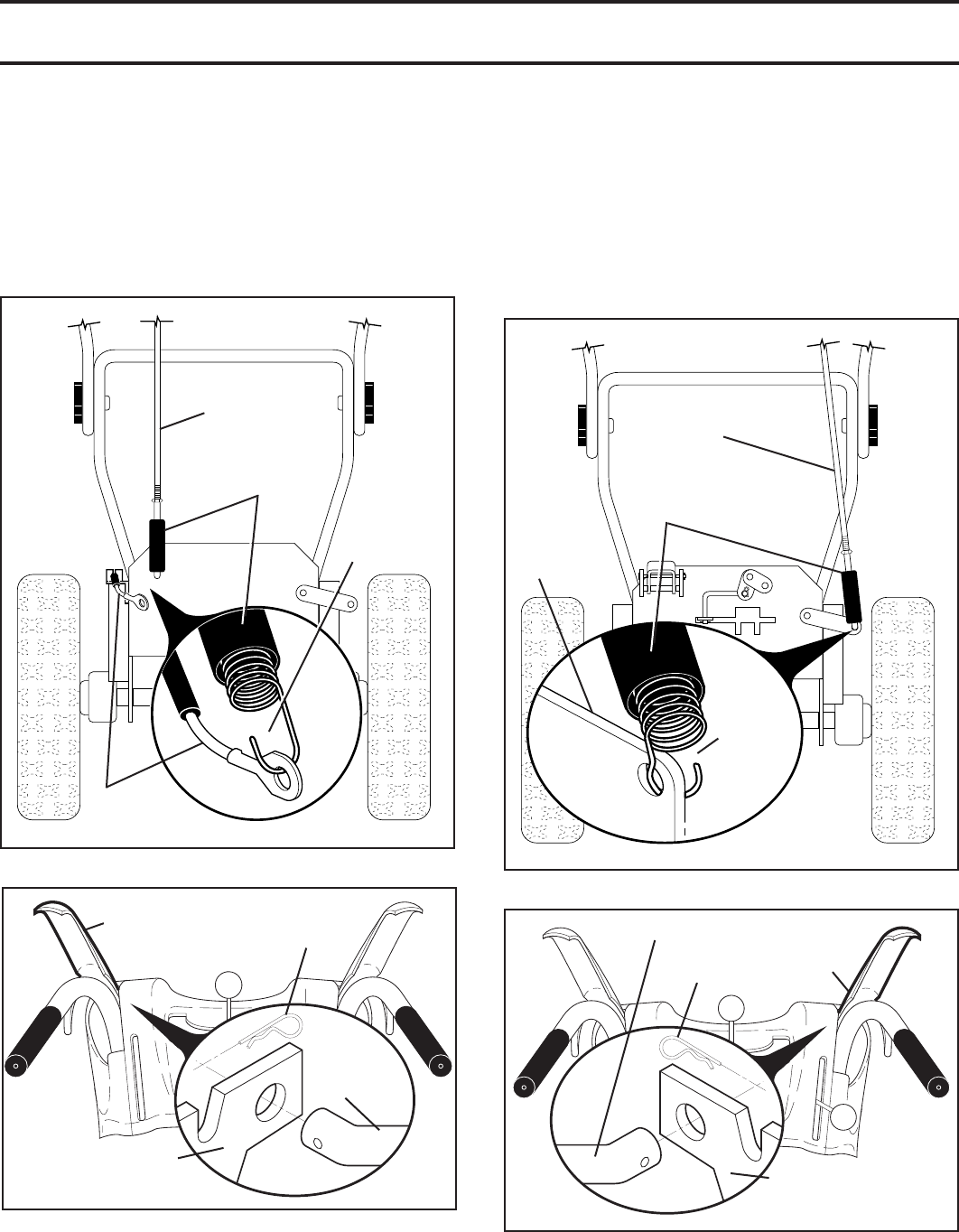
AUGER
CONTROL
ROD
CONTROL
ARM
RUBBER
SLEEVE
LOOP
OPENING
UP
Fig. 5
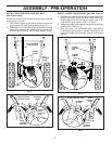
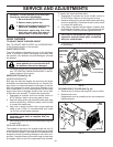
INSTALL TRACTION DRIVE CONTROL ROD
(See Figs. 3 and 4)
The traction drive control rod has the long loop on the end
of the spring as shown.
1. Slide rubber sleeve up rod and hook end of spring into
eye of cable with loop opening down as shown.
2. With top end of rod positioned under left side of control
panel, push rod down and insert top end of rod into hole
in drive control bracket. Secure with retainer spring.
TRACTION DRIVE
CONTROL ROD
CABLE
RUBBER
SLEEVE
Fig. 3
LOOP
OPEN ING
DOWN
ASSEMBLY / PRE-OPERATION
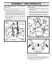
TRACTION
DRIVE
CON TROL
ROD
DRIVE
CONTROL
BRACKET
RETAINER
SPRING
TRACTION DRIVE
CON TROL LEVER
FIG. 4
AUGER
CONTROL
LEVER
AUGER CONTROL ROD
AUGER
CONTROL
BRACKET
RETAINER
SPRING
FIG. 6
INSTALL AUGER CONTROL ROD (See Figs. 5 and 6)
1. Retrieve vinyl sleeve and spring from bag of parts and
retrieve the auger control rod from carton chute tray.
Slide straight rod end through the small hole in the
vinyl sleeve. Hook spring in hole in rod end.
2. Hook end of spring into control arm with loop opening
up as shown. (See Fig. 5)
3. With top end of rod positioned under right side of
control panel, push down on rod and insert end of rod
into hole in auger control bracket. Secure with retainer
spring.