


7
ASSEMBLY (starts at page 32)
ASSEMBLY (starts at page 33)
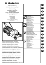
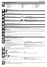
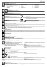
DESCRIPTION (starts at page 31)
ASSEMBLY OF GRASS CATCHER (starts at page 31)
OPERATION (starts at page 35)
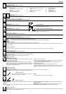
ENGINE ADJUSTMENTS
Refer to the engine manufacturer's maintenance manual.
CAUTION:- 0.6l Oil must be added to the engine before use.
ASSEMBLY REAR DEFLECTOR (starts at page 31)
ADJUSTMENT OF CUTTING HEIGHT (starts at page 34)
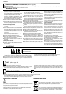
l Always operate with the deflector or grasscatcher in the correct position.
l Always stop the engine before removing the grasscatcher or adjusting the height of cut.
l Never place your hands or feet underneath the deck or into the rear grass discharge chute while the engine is running.
Before mowing, remove all foreign objects from the lawn which may be thrown by the machine. While mowing, stay alert for any foreign objects which may have been
missed.
Never lift the rear of the mower while starting the engine or during normal operation.
Never place your hands or feet underneath the deck or into the rear discharge chute while the engine is running.
SAFETY PRECAUTIONS (starts at page 34)
Keep the engine stop lever (14) depressed during machine operation. When the lever is
released, the engine stops.
MOWING
To cut the grass, push the lawn mower manually or insert the automatic advance
ENGLAND
AA
AA
A
BB
BB
B
DD
DD
D
EE
EE
E
FF
FF
F
HH
HH
H
GG
GG
G
II
II
I
JJ
JJ
J
M
LL
LL
L
KK
KK
K
MM
MM
M
NN
NN
N
OO
OO
O
STARTING THE ENGINE
Once the machine has been set up properly, start the engine as follows:
a)
Engines with choke system:
when the engine is cold, position the accelerator lever (13) on START
b)Operate the engine stop lever (14) to prepare the engine for start, keep lever
pressed against handle while starting and using the machine - it operates the
engine brake.
ELECTRICAL STARTING
:
lInsert the plug (G) in the socket (H) on the engine. While holding the engine stop lever (14).Turn the ignition key (17).
CAUTION:
The blade starts turning as soon as the engine is started.
gear.
How to insert automatic advance: Lift up the clutch handle (18) and keep it pressed in
position.
CAUTION:
Engage the gear only when the engine is running.
How to disengage advance: Release the clutch handle.
Self-Propelled/ Electric Start Lawnmower.
Remove the bail arms, attach cables as shown and re-fit the bail arms, if applicble.
Assemble the handle fit the levers with the pins and clips provided, assemble the
wheels as shown and throttle if supplied.
(starts at page 34)
(starts at page 35)
(starts at page 35)
(starts at page 34)
(starts at page 35)
1 Upper handles 7 Deck 13 Throttle lever
2 Lower handles 8 Adjusting levers for cutting height 14 Engine stop lever
3 Fastening knobs for upper handles 9 Spark plug 15 Reduction gear
4 Grass catcher 10 Fuel cap 16 Console
5 Oil filler cap 11 Engine start-grip 17 Ignition key
6 Oil drain plug 12 Rear deflector 18 Clutch lever
CC
CC
C
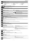
c)
Engines with primer system:
Press the fuel-enrichment pump (Picture 'K' item 31) located on the carburettor 3 or 4
times position the accelerator lever (13) on MAX.
For further information and explanations, read carefully the user instruction manual of
the engine.
d) Start engine.
MANUAL STARTING:
(While holding the engine stop lever (14)).
lHold the engine start-grip (11) and pull the starter rope gently until you feel the resistance
caused by compression. Return the starter rope slowly then pull the handle firmly towards
you to its full extent.
Keep the engine stop lever (14) depressed during machine
operation. When the lever is released, the engine stops.
MOWING
To cut the grass, push the lawn mower manually
(starts at page 35)
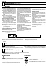
PP
PP
P
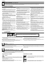
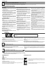
Important: If, when you press the clutch lever, the automatic advance gear does not engage, the clutch cable should be adjusted by inserting the spring (P) in one of the
subsequent holes in the plate (R) (or in the hole "S" .
(starts at page 36)
Manual lawn mower
Remove the bail arms, attach cables as shown and re-fit the bail arms, if applicble..
Assemble the handle fit the levers with the pins and clips provided, assemble the
wheels as shown and throttle if supplied.
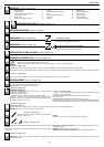
Assemble the spring into the rear deflector as shown in figure D1, insert the rod through the holes on the rear deflector and spring as shown in figure D2.
Locate the rod into the mounting bracket as shown in figure D3, push down the sprint as shown in figure D4 to locate it into the slot which tensions the rear deflector.