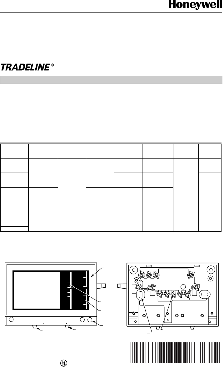
MOUNTING
HOLES (4)
WIRING TERMINAL
(UP TO 12)
M2960A
BACK OF DEVICE
80
70
60
50
EM. HEAT HEAT OFF COOL
80
70
60
50
AUTO ON
FAN
EM. HEAT AUX. HEAT
CHECK
FRONT OF DEVICE
FAN SWITCH
SYSTEM SWITCH
COVER
THERMOMETER
SET POINT
SCALE
LED (UP
TO THREE)
T841A Heating-Cooling
Heat Pump Thermostat
X-XX UL
INSTALLATION INSTRUCTIONS
®U.S. Registered Trademark
Copyright © 1997 Honeywell Inc. • • All Rights Reserved
APPLICATION
The T841A Heating-Cooling TRADELINE® Thermostat
provides 24 Vac control of two-stage heating and one-
stage cooling in heat pump systems, using manual
changeover. This thermostat provides SYSTEM switch
selections of EM. HEAT-HEAT-OFF-COOL and FAN
switch selections of AUTO-ON. See Fig. 1. See Table 1 for
T841A TRADELINE® specifications.
Test holes are provided on the front of the thermostat to
accommodate test meter probes without removing the
thermostat from the wall. Remove the cover of the
thermostat to expose the test holes, which are labeled to
correspond with the terminals on the back of the
thermostat.
Table 1. T841A TRADELINE® Specifications.
Fig. 1. External view of T841A.
a
EM. HEAT LED also indicates compressor malfunction.
b
Premier White® color.
c
Sold only in Australia: degrees C.
d
CHECK LED indicates compressor malfunction.
OS Number
LED
Indication Changeover
Heat
Anticipation
Terminal
Designations Remarks
System
Switch
Auto Fan
in EM.
HEAT
T841A1308 EM. HEAT
a
,
AUX. HEAT
Manual Cool
or Heat
Stage 2 fixed,
0 to 1.5A
G, R, W
2
, E,
L, B, X, Y, O
Use when E
and W
2
are
jumpered.
EM. HEAT,
HEAT, OFF,
COOL
No
T841A1316 G, R, E, L, X
W
2
, B, W1,
Y
1
, O
Does not
replace
T841A1068.
Yes
T841A1423
b
EM. HEAT,
AUX. HEAT,
CHECK
d
Stage 2
adjustable, 0.1
to 1.2A
W
3
, G, R, W
2
,
E, L, B, X, Y,
O
Not for systems
with E to W
2
jumper
T841A1464
b,c
T841A1498 EM. HEAT Stage 2 fixed,
0 to 1.5A
G, R, W, H, B,
X, O, Y
Exact
replacement for
York model no.
2TH11703324
T841A1506
b
69-0452-8


