


ENGLISH - 6
The chain brake can be activated in two modes: the
first using the left wrist by pushing forwards, or when
it comes into contact with the brake system as a result
of kickback; or by inertia, in the case of particularly
violent kickback.
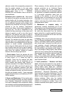
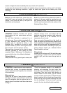
When the machine is used with the bar in horizontal
position, for example during tree felling, the chain
brake offers less protection, because it can be
activated by inertia only, since the user’s hand is
outside the range of action of the front hand guard
(fig.3).
N.B.: When the chain brake is activated, a safety
switch cuts off all current to the motor.
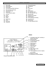
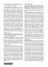
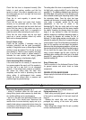
CHAIN CATCHER
This machine is equipped with a chain catcher (fig.4)
located under the pinion. This mechanism is
designed to arrest the backward chain movement in
the case of chain breaking or derailing. These
situations can be avoided by ensuring correct chain
tension (Refer to chapter “D. Assembly/disassembly”).
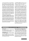
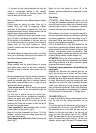
REAR HAND GUARD
This acts to protect(fig.5) the hand in the case of
chain breaking or derailing.
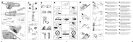
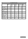
D. ASSEMBLY / DISASSEMBLY
2,3,6,7,8,9,12
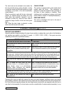
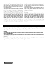
BAR AND CHAIN ASSEMBLY
Assembly methods change according to the type of your machine- so please take care to refer to the illustrations
and machine type marked on the label (A- Legend – 9 [ES15 / ES16 / ES18] ), Take great care when
assembling to ensure this is performed correctly.
FOR ES 15 / ES 16 FOR ES 18
1. Control that the chain brake is not activated. If so, deactivate it.
2a. Unscrew the bar retaining nuts and remove
the chain cover.
2b. Unscrew the bar retaining knob and remove the
chain cover.
3a. Mount the bar on the bar retaining screws
pushing it as far backward towards the pinion
as possible.
3b. Mount the bar on the bar retaining screw pushing
it as far backward towards the pinion as possible.
4. Oil the chain, then position it over the pinion, making it slide into the bar guide groove, beginning with
the upper part. Attention! Control that the sharp side of the cutting teeth face in a frontward direction on
the upper part of the bar; Set the chain tensioner pin in the chain tensioner pin housing. Mount the chain
cover making sure that the drive teeth of the chain are engaged in the pinion and in the guide groove.
5a. Close the bar retaining nuts, screwing by
hand.
5b. Screw the bar retaining knob loosely tightened.
6a. To spread the chain screw the chain
tensioner screws in a clockwise direction, to
loosen tension, screw in an anti-clockwise
direction (when performing this operation
maintain the bar nose raised upwards)
6b. To spread the chain screw the chain tensioner
knob in a clockwise direction, to loosen tension, screw
in an anti-clockwise direction (when performing this
operation maintain the bar nose raised upwards)
7 Spread the chain until the tension is correct; that is, when the chain is pulled upwards, the drive tooth
rise to the same level as the bar. (the chain must never droop on the underside of the bar)
8a. Tighten the bar retaining nuts using an
appropriate tool.
8b. Tighten the bar retaining knob strongly.
Tensioning the chain too tightly will overload the motor and cause damage, insufficient tension can provoke
chain derailing, whereas a chain tightened correctly provides the best cutting characteristics and prolonged work
life. Check the tension regularly because the chain length tends to stretch with use (especially when the chain is
new; after the first assembly, the chain tension must be controlled after 5 minutes machine operation); in any