


TECHNICAL DATA BROCHURE ZTR 310
.IMPORTANT - READ OPERATOR'S MANUAL BEFORE OPERATION.
Seat Adjustment
Loosen Bolts on sliding brackets under each side of seat, slide seat forward or rearward to desired position.
Re-tighten bolts. Do not operate mower with
bracket bolts in a loose condition.
Mower Blade Operation
To start mower blades, move lever on floor slowly to "ENGAGE" position. To stop mower blades,
move lever on floor slowly to "DISENGAGE" position.
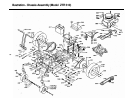
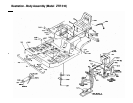
Body Removal
1. Disconnect throttle cable from engine.
2. Disconnect the rear wiring loom (P/N 4109) from the body by lightly squeezing the Econo-Seal plug. This
Is located at the left rear of the body.
3. Note: Loosen bolts that hold body switch (P/N 4079) and slide switch away from engaging rod. Tighten one
bolt just enough to hold switch 1n this position until body is reassembled.
4. Remove 4 control lever bolts and remove upper control levers (P/N 1689 i 1690).
5. Remove engaging handle (P/N 6089) by removing bolt and nut under handle.
6. Remove the 2 attach nuts on floor of body and 2 sheet metal screws at the rear of body.
7. Place height adjustment lever in vertical position, engage parking brake and
carefully lift body up and
off chassis.
8. Reverse the above procedure for assembly.
Safety Checks
With the mower deck in the engaged position slide the body switch (P/N 4079) toward
the engaging rod (P/N 6038) until the switch leaf just makes contact with the
switch button. Tighten both bolts 1n switch bracket.
with mower deck engaged, attempt to start engine in all cutting height positions.
if engine starts in any cutting height position, re-adjust the switch. Disengage
the mower deck and start the engine In each cutting height position. If engine
fails to start in any cutting height position, re-adjust switch.
with operator in normal mowing position, engage mower deck and remove weight from
seat. The engine should stop. Repeat this procedure in each cutting height
position. If engine does not stop when operator rises from seat in each cutting
height position, return to an authorized Dixon dealer for adjustment or repairs.
Parking Brake Adjustment
Remove body as described above. Tighten nut on brake rod (P/N2533) (Located 1n
front of the transaxle on
each side.), just enough to prevent brake from slipping
when engaged.
CAUTION: Over tightening may
cause premature wear on brake band (P/N 5085).
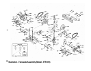
Mower Drive Belt Adjustment
Belt tension for mower drive belt (P/N 2412) is adjusted by loosening nut on the connecting arm assembly
(P/N 2148) and turning bolt to achieve desired tension. Re-tighten nut. Tension should be checked with
belt 1n engaged position.
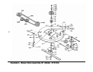
Removing Mower Deck
1. Remove engaging handle (P/N 6089) by removing bolt and nut under handle.
2. Loosen belt keeper (P/N 2234) located under engine by loosening 2 rear engine mount bolts to allow mower
deck drive belt to come free of rear pulley. Re-tighten belt keeper.
3. Remove 4 attach pins (P/N 6107) and clips fro* 4 mower deck attach points
and 2 stabilizer bars (P/N 6159).
4. Raise front of mower chassis to allow mower deck engaging rod (P/N 6038) to clear the chassis. At this time,
mower may be rolled free of mower deck for service and/or replacement.
5. To re-install, reverse the above procedure.
Removing Hower Cutter Blade
Secure mower cutter blade (P/N 2406) from turning (observe blade position when removing) remove blade bolt
from center of blade.
DIXON
INDUSTRIES,
INC.
BOX
494
COFFEYVILLE,
KANSAS
67337-0494
(316)
251-2000
P/N 8536 (H/83)