


2006-12-08
5011646001-CTE1
Instruction Sheet
Thank you very much for purchasing DELTA CTA series. Please read this instruction sheet before using your CTA
series to ensure proper operation and please keep this instruction sheet handy for quick reference.
¾ DANGER! Caution! Electric Shock!
¾ When the power is on, DO NOT touch the AC terminals in case an electric shock may occur.
¾ Make sure the power is disconnected when you check the unit inside.
¾ CTA series is an OPEN-TYPE device. They are intended for installation completely within an overall panel and are for use
in counting or timing application. If it will cause serious injury to workers or damage on other equipments when used in a
dangerous environment, please make sure it is installed in an automatic safety protection device.
1.
Precaution
1. Always use recommended solder-less terminals: Fork terminal with isolation (M3 screw, width 7.0mm), hole (diameter
3.2mm). Screw size: M3x6.5 (with 6.8x6.8 square washer). Recommended tightening torque: 0.4 N.m (4kgf.cm).
Applicable wire: solid/twisted wire of 2mm
2
, 12AWG to 24 AWG. Please be sure to tighten them properly.
2. Prevent dust or metallic debris from falling into the device and cause malfunctions.
3. DO NOT modify or uninstall the device.
4. DO NOT use empty terminals.
5. Make sure the wires are correctly connected to proper terminals.
6. Keep away from high-voltage and high-frequency environment during installation in case of interference.
7. Prevent using the device in premises which contain:
․Dust or corrosive gas ․High humidity ․High radiation ․Vibration and shock
8. CTA series is an open-type device. Make sure to install it in an enclosure to prevent dust, humidity in case of an electric
shock.
9. Please make sure the power cables and signal device are installed correctly before switching on the power; otherwise
serious damage may occur.。
10. DO NOT touch the terminals or repair the device when the power is on; otherwise an electric shock may occur.
11. Please wait for one minute after the power is switched off to allow the capacitor to discharge and DO NOT touch the
internal wiring within this period.
12. Use dry cloth to clean the device. DO NOT use acid or alkaline liquid to clean the device.
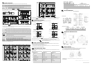
2. Display, Indicators and Keys
Reset 2 indicator
Reset 1 indicator
Key protect 2 indicator
Output 2 indicator
Key protect 1 indicator
Output 1 indicator
Special function indicator
Lock key
Reset key
Mode and number shift key
PV(Present Value) display
SV(Set Value) display
Timer function indicator
Counter function indicator
Tachometer function indicator
Up/Down key
LCD Display and indicators
RST 1/2
Light on when reset signal is detected BATCH
“Batch Counting Mode” in Counter and Tachometer function
K/P 1/2
Light on when key-protected mode is enabled
SET 1 2
SV1, SV2 display
OUT 1/2
Light on when output is executing TAC
Light on when Tachometer function is executing
H M S
Hour, minute, second, unit of timer, displayed
in Timer function
CNT
Light on when Counter function is executing
TOTAL
“Total Counting Mode” in Counter and
Tachometer function
TMR
Light on when Timer function is executing
Key Operation
Increase and decrease SV or change parameter settings.
Left move 1 digit of the selected digit. The indicator of the selected digit will flash.
MODE
Save the set parameters or switch among functions.
LOCK
Prevent settings from being changed. Key-protected mode still works after the power is switched off. Press
LOCK to enter key-protected mode. In non-key-protected status, press LOCK to enter Lock 1. In Lock 1, press
LOCK again to enter Lock 2. Press
MODE
and at the same time to disable key-protected mode. (Lock 1)
disables the functions of all keys. (Lock 2) allows users to change SV and functions of RESET remain.
LOCK only functions in non-key-protected status.
RESET
Clear and reset PV.
Modes: Operation Mode and Configuration Mode
Operation
When the power is on, the timer/counter/tachometer is in the operation mode. Press to change SV, or
to make change on a desired digit. The indicator of the selected digit will flash. After the change is made,
press
MODE
to save the setting. If SV or parameters are not changed, press
MODE
once to switch between
SET1 and
SET2.
Configuration
Press
MODE
in operation mode for more than 3 seconds to enter configuration mode. Press
MODE
once to switch
among parameters. To return to operation mode, press
MODE
for more than 3 seconds.
3. Ordering Information
CTA
2
3
4
5
6
1
n Product name
CTA: Delta Counter/Timer/Tachometer A series
q Preset stage 0: 2 preset stage
o Panel size 4: 48mm x 48mm 1/16DIN r Communication
0: none
p Output 2 0: NPN; 1: Relay s Power supply A: AC 100~240V
4.
Specification
Power input
AC 100~240V, 50/60Hz
Input voltage range
85% to 110%, rated voltage
Power consumption
Less than 10VA
External power supply
12Vdc ±10%, 100mA
Display
Double-line, 6-digit negative transmissive LCD display
Non-voltage input (NPN): ON impedance 1K ohm max. ON residual voltage: 2V max.
Input signal
Voltage input (PNP): High level: 4.5 to 30Vdc, Low level: 0 to 2Vdc
Relay: SPST max.250Vac, 5A (resistance load)
Output 1
Transistor: NPN open collector. When 100mA /30Vdc, residual voltage=1.5Vdc max.
Relay: SPDT max.250Vac, 5A (resistance load)
Output 2
Transistor: NPN open collector. When 100mA /30Vdc, residual voltage=1.5Vdc max.
Dielectric strength
2000Vac 50/60 Hz for 1 minute
Vibration resistance
Without damage: 10~55Hz, amplitude=0.75mm, 3 axes for 2 hours
Shock resistance
Without damage: drop 4 times, 300m/s
2
, 3 edges, 6 surfaces and 1 corner
Ambient temperature
0
o
C to +50
o
C
Storage temperature
-20
o
C to +65
o
C
Altitude
2000m or less
Ambient humidity
35% to 85% RH (non-condensing)
Pollution degree
Degree 2
5.
Parameters in Configuration Mode
Timer
Select a
function
MODE
Setup Timer
function,
(counting up
or down)
MODE
Select
output
mode of
Timer
MODE
Setup the
displayed
unit of timer
MODE
Setup the
pulse width
of output 1
MODE
Reset min.
pulse width
MODE
Select input
type (PNP
or NPN)
MODE
Back to
“select a
function”
Counter
Select a
function
MODE
Select
counting
modes
MODE
Setup input
mode of
Counter
MODE
Setup output
mode of
Counter (not
dual output)
MODE
Setup dual
output counting
mode (dual
output)
MODE
Setup counting
speed
MODE
Setup the
pulse width of
output 1
MODE
Back to
“select a
function”
Select input
type (PNP or
NPN)
MODE
Reset min.
pulse width
MODE
Save data or
not while
switching off
power
MODE
Setup pre-scale
value
MODE
Setup the
decimal point
MODE
Setup the
pulse width of
output 2
MODE
Tachometer
Select a function
MODE
Setup output mode
of Tachometer
MODE
Setup counting
speed
MODE
Setup the decimal
point
MODE
Setup pre-scale value
MODE
Back to “select a
function”
Select input type
(PNP or NPN)
MODE
Reset min. pulse
width
MODE
!
Setup the average of
input data
MODE
Setup the delay time
while switching on
power
MODE
Timer + Counter Mixed
Select a
function
MODE
Setup Timer
function,
(counting
up or down)
MODE
Setup
output
mode of
timer
MODE
Setup the
displayed
unit of
timer
MODE
Setup
input
mode of
Counter
MODE
Setup
output
mode of
Counter (not
dual output)
MODE
Setup
counting
speed
MODE
Setup the
pulse width
of output 1
MODE
Back to
“select a
function”
Select
input type
(PNP or
NPN)
MODE
Reset
min.
pulse
width
MODE
Save data
or not
while
switching
off power
MODE
Setup
pre-scale
value
MODE
Setup
the
decimal
point
MODE
Setup the
pulse
width of
output 2
MODE
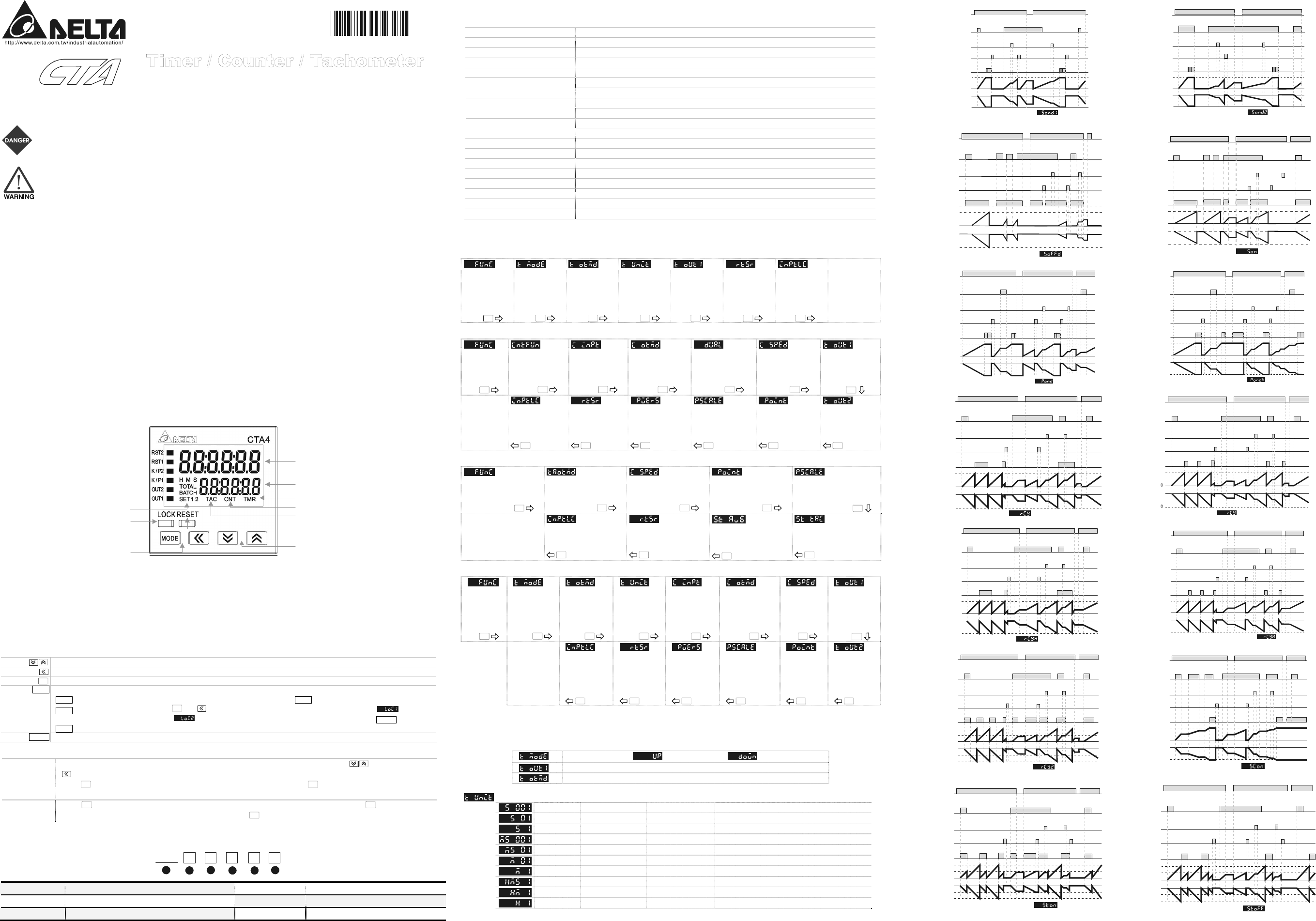
6.
Timer Function
There are counting up/down modes, several counting units and output modes to choose from in timer function.
Select counting up or counting down
Setup the output time of timer, from 0 to 99.99 secs. 0= Hold output
Setup output modes
Setup the counting unit of the timer.
sec 0.01~9999.99
A unit = 10ms. Max. counting = 9999.99 secs.
sec 0.1~99999.9
A unit = 0.1sec. Max. counting = 99999.9 secs.
sec 1~999999
A unit = 1 sec. Max. counting = 999999 secs.
min,sec 0.01~9959.99
A unit = 0.01 sec.
Max. counting = 5999.99 secs.
min,sec 0.1~99959.9
A unit = 0.1 sec. Max. counting = 59999.9 secs.
min 0.1~99999.9
A unit = 0.1 min. Max. counting = 99999.9 mins.
min 1~999999
A unit = 1 min. Max. counting = 999999 mins.
hr,min,sec 1~995959
A unit = 1 sec. Max. counting = 359999 secs (100hr)
hr,min 1~999959
A unit = 1 min. Max. counting = 35999999 secs (10000hr)
hr 1~999999
A unit = 1 hr. Max. counting = 999999 hrs
Power signal
Start signal
Pause signal
Clear signal
Up
Down
0
0
SV
SV
Signal On Delay 1
t
t
Output signal
Power signal
Start signal
Pause signal
Clear signal
Output signal
Up
Down
0
0
SV
SV
Signal On Delay 2
tt
Power signal
Start signal
Pause signal
Clear signal
Output signal
SV
0
Up
Down
SV
0
Signal Off Delay
Power signal
Start signal
Pause signal
Clear signal
Output signal
SV
0
Up
Down
SV
0
Signal On
Power signal
Start signal
Pause signal
Clear signal
Output signal
Up
Down
SV
SV
0
0
Power On Delay
t
tt
Power signal
Start signal
Pause signal
Clear signal
Output signal
Up
Down
SV
SV
0
0
Power On Delay Hold
tt t
t
Power signal
Start signal
Pause signal
Clear signal
Output signal
Up
Down
SV
SV
Repeat Cycle
0
0
timer output set as 0
Power signal
Start signal
Pause signal
Clear signal
Output signal
Up
Down
SV
SV
Repeat Cycle
tt t
timer output not set as 0
Power signal
Start signal
Pause signal
Clear signal
Output signal
Up
Down
SV
SV
0
0
Repeat Cycle Hold
Timer output set as 0
Power signal
Start signal
Pause signal
Clear signal
Output signal
Up
Down
SV
SV
0
0
RCYH timer output not set as 0
tt
t
Power signal
Start signal
Pause signal
Clear signal
Output signal
Up
Down
SV1
SV1
SV2
SV2
0
0
Repeat Cycle 2
Power signal
Start signal
Pause signal
Clear signal
Output signal
Up
Down
0
SV
SV
0
Signal Cumulate
Power signal
Start signal
Pause signal
Clear signal
Output signal
Up
Down
SV1
SV2
SV1
0
0
SV2
Signal Twin ON-Start
Power signal
Start signal
Pause signal
Clear signal
Output signal
Up
Down
SV1
SV1
SV2
SV2
0
0
Signal Twin OFF-Start