


8
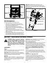
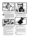
Auger Drive Control
The auger drive control is located on the left handle.
Squeeze the control grip to engage the augers.
Release to stop the snow throwing action. (Traction
control must also be released.) See Figure 8.
Trigger Lever
The left and right turn triggers are located on the
underside of the handles and are used to assist in
steering your snow thrower. Squeeze the right trigger
lever when turning right and the left trigger lever when
turning left. See Figure 8.
Chute Tilt Control
The distance snow is thrown can be changed by
adjusting the angle of the chute assembly. Move the
chute tilt control forward to decrease the distance,
toward the rear to increase. See Figure 8.
Skid Shoe
The position of the skid shoe is determined by the
condition of the ground from where snow has to be
removed. See Figure 8.
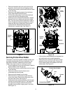
Shift Lever
The shift lever is located in the center of the handle
panel and is used to determine both ground speed and
direction of travel. It can be moved into any of eight
positions. See Figure 8.
Forward
Your snow thrower has six forward (F) speeds. Position
number one (1) is the slowest. Position number six (6)
is the fastest.
Reverse
Your snow thrower has two reverse (R) speeds. R1 is
the slower, while R2 is the faster of the two.
IMPORTANT:
Always release tractional control before
changing speeds.
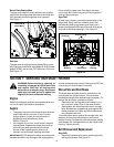
Electric Chute-Rotation Switch
The electric chute-rotation switch is located on the left
side of the snow thrower dash panel. See Figure 8.
To change the direction in which discharged snow is
thrown, proceed as follows:
• Push the toggle switch to the left to rotate the chute
counterclockwise.
• Push the toggle switch to the right to rotate the
chute clockwise.
IMPORTANT:
Release the switch once the chute has
completed its rotation cycle in either direction. Failure to
do so can result in damage to the electric chute motor
and/or its drive gear.
Headlight
The headlight is on whenever the engine is running.
Throttle Control
The throttle control is located on the engine. It regulates
the speed of the engine and will shut off the engine
when pushed down completely. See Figure 8.
Safety Ignition Key
The safety ignition key must be fully inserted in the
switch before the unit will start. Remove the ignition key
when the snow thrower is not in use. See Figure 8.
IMPORTANT:
Do NOT attempt to turn the key.
Fuel Shut-off Valve
The fuel shut-off valve, located under the fuel tank,
controls fuel flow from the tank. Always make certain it
is in the Open (vertical) position before attempting to
start the engine. See Figure 8.
Heated Handles Switch
This switch is located on the right side of the snow
thrower dash panel. To activate the heated handles,
toggle the switch to the right to generate heat within the
handle grips. Toggle the switch to the left to the OFF
position after using the snow thrower. See Figure 8.
NOTE: The heated handles grips are a compliment to,
not a substitute for, proper cold weather outerwear for
the operator’s hands. It is recommended that the snow
thrower operator wear gloves/mittens to avoid
extremities of winter while operating this equipment.
SECTION 4: OPERATING YOUR SNOW THROWER
Before Starting
WARNING: Read, understand, and follow
all instructions and warnings on the
machine and in this manual before
operating.
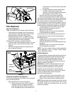
Gas And Oil Fill-up
Service the engine with gasoline and oil as
instructed in the separate engine manual packed with
your snow thrower. Read instructions carefully.