


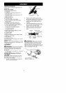

HANDLEBAR ASSEMBLY
,_ DANGER: RISK OF CUT. To avoid
serious injury, the barrier portion of the
handlebar must be installed as shown
on the upper shaft of the powerhead to
provide a barrier between operator and
the spinning blade. Attach handlebar
mounting bracket above arrow on
safety warning decal on the upper
shaft (powerhead end of unit). Ensure
handlebar is positioned on mounting
bracket at the end of the arrow on the
handlebar decal.
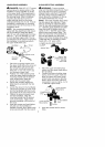
NOTE: Two mounting brackets are in-
cluded with this attachment. Both brack-
ets are provided to adapt this attach-
ment for use with powerheads that have
either a 1" (2.5 cm) diameter or a 7/8"
(2.2 cm) diameter upper shaft. The cor-
rect bracket must be used to ensure that
the handlebar is mounted securely to
the upper shaft before use.
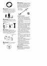
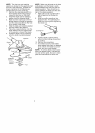
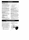
Handlebar ._ J_ _ Screw
_et Cover
Bracket .'
I
1. Place the mounting bracket over
the upper shaft above the arrow on
the safety label. Be sure to use
the correct mounting bracket for
either the 1" (2.5 cm) or 7/8" (2.2
cm) diameter upper shaft.
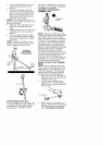
2. Position one of the bracket covers
under the upper shaft and align the
mounting bracket and the bracket
cover screw holes. Insert two
screws into the screw holes.
3. Secure the mounting bracket by
tightening the screws with the hex
wrench.
4. Locate the decal on the handlebar.
This decal includes an arrow. Posi-
tion the handlebar with the mount-
ing bracket at the end of the arrow.
5. Position the second bracket cover
over the handlebar. Align the
mounting bracket and the bracket
cover screw holes. Again make
sure the handlebar is at the end of
the arrow.
6. Insert two screws and hand tighten
only. Be sure the handlebar is
installed correctly; then, tighten each
screw securely with the hex wrench.
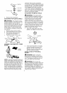
SHOULDER STRAP ASSEMBLY
_bWARNING: Proper shoulder
strap and handlebar adjustments must
be made with the engine completely
stopped before using unit. The shoul-
der strap clamp must be installed as
shown above the handlebar on the up-
per shaft (powerhead end of unit).
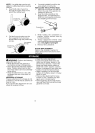
NOTE: The lower shoulder strap clamp
has two spacer tabs attached. These
tabs are provided to adapt this attach-
ment for use with powerheads that have
a 1" diameter upper shaft (the shoulder
strap clamp will not tighten down se-
curely on the 1" diameter upper shaft
without using these spacer tabs). The
tabs must be broken off completely be-
fore use and placed over the screw
holes on the lower shoulder strap clamp.
These tabs are not needed for power-
heads with a 7/8" upper shaft.
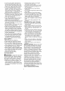
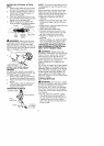
LOWER SHOULDER STRAP
CLAMP
1,
2.
.,_L_L_ / Spacer Tabs
positioned for use
on 1" diameter
upper shaft
Place the upper shoulder strap
clamp over the upper shaft above
the handlebar.
Position the lower shoulder strap
clamp under the upper shaft and
align the upper and lower clamp
screw holes (use spacer tabs be-
tween upper and lower clamps if
necessary to secure clamp, i.e. for
1" diameter upper shaft).
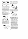
POWERHEAD
END
Strap Clamp
Lower Shoulder | ATTACHMENT
Strap Clamp n _' END
!
Screws
3. Insert two screws into the screw
holes.
6