


IMPORTANT: To help avoid misalignment of holes in
tractor frame, lower the mower deck to the ground or
disconnect it from the front brackets before removing
any bolts from the tractor frame.
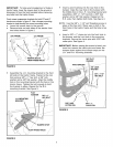
Front mower suspension brackets for both GT and LT
tractors are shown in figure 2. Use a bumper mounting
bracket to help identify the correct mounting holes.
• Lower the mower deck to the ground.
• Remove bolts on both sides of the tractor from
two holes shown in figure 2.
(GT) FRAME
(LT) FRAME
o
REMOVE BOLTS
FROM THESE HOLES
FIGURE 2
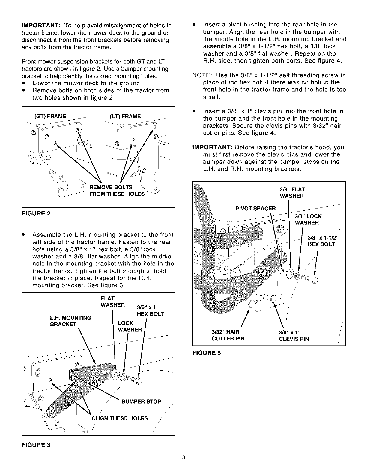
Assemble the L.H. mounting bracket to the front
left side of the tractor frame. Fasten to the rear
hole using a 3/8" x 1" hex bolt, a 3/8" lock
washer and a 3/8" flat washer. Align the middle
hole in the mounting bracket with the hole in the
tractor frame. Tighten the bolt enough to hold
the bracket in place. Repeat for the R.H.
mounting bracket. See figure 3.
L.H. MOUNTING
BRACKET
FLAT
WASHER 3/8" x 1"
HEX BOLT
LOCK
WASHER
/
ALIGN THESE HOLES
/
FIGURE 3
Insert a pivot bushing into the rear hole in the
bumper. Align the rear hole in the bumper with
the middle hole in the L.H. mounting bracket and
assemble a 3/8" x 1-1/2" hex bolt, a 3/8" lock
washer and a 3/8" flat washer. Repeat on the
R.H. side, then tighten both bolts. See figure 4.
NOTE: Use the 3/8" x 1-1/2" self threading screw in
place of the hex bolt if there was no bolt in the
front hole in the tractor frame and the hole is too
small.
Insert a 3/8" x 1" clevis pin into the front hole in
the bumper and the front hole in the mounting
brackets. Secure the clevis pins with 3/32" hair
cotter pins. See figure 4.
IMPORTANT: Before raising the tractor's hood, you
must first remove the clevis pins and lower the
bumper down against the bumper stops on the
L.H. and R.H. mounting brackets.
3/8" FLAT
WASHER
PIVOT SPACER F_
3-/8"LOCK
WASHER
!
3132"HAIR
COTTER PIN
3/8"x 1"
CLEVIS PIN
FIGURE 5