MODEL: 62BK244CBK, 62BK244CCN,
62BK244CCY, 62BK244CMP,
62BK244TBK, 62BK244TCY,
62BK244TGK, 62BK244TMP
RECESSED MOUNTED,
STEEL MEDICINE CABINETS
INSTALLATION of CABINET
1. Carefully remove all packing material. Place hardware
packages, shelves and door aside until needed. Hardware
and shelves are located in the fillers identified by “Hardware
Enclosed” tape.
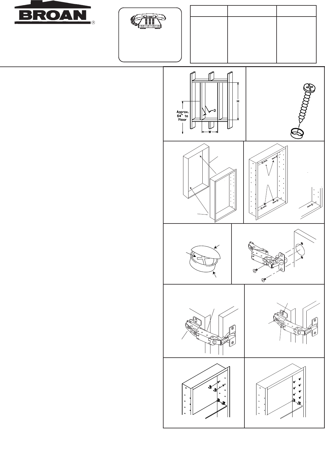
2. Determine desired location of cabinet on wall. Mark wall to
show wall opening size (see dimension chart). Generally, the
recommended height to the center of the cabinet is 64” from
the floor. (Fig. 1)
3. CAUTION: Wall studs, plumbing or electrical lines that
interfere must be removed or relocated. Cut wall opening,
being careful not to damage the surrounding wall surface.
Insert framing to support all plaster board edges.
4. Prepare the mounting screws by placing the screws into the
plastic bases. (Fig. 2)
5. Note: For ease of installation, an additional person is
recommended. Insert cabinet into wall opening. (Fig.3)
Ensure the cabinet is plumb and level. If necessary use a
carpenter’s level and shim corners of cabinet. Secure to wall
studs through the four (4) mounting holes inside cabinet,
using the screws that have been placed into the plastic
bases. (Fig. 4) Do not over tighten the mounting screws as
the body side wall may bend and prevent proper shelf
installation. Only tighten screws until they are flush with the
body.
6. Snap the screw covers over the screw bases. (Fig.5)
INSTALLATION of DOORS
1. Remove hinges and screws from hardware bag. Mount
hinge unit on door as shown in Fig. 6 securing with screws
provided.
2. Install the door by inserting door side of the hinge into the
bracket on the body shown in Fig. 7.
3. Check door for proper alignment. If the door needs to be
adjusted please refer to the adjustment procedures in Fig. 8.
INSTALLATION of SHELVES, HOLE PLUGS AND
BUMPERS
1. Select where you want the shelves to be placed.
2. Insert two (2) shelf brackets at each end of the shelf
location. (Fig. 9).
3. Set shelves in place on the shelf brackets, pressing down
on the shelf to lock in place. (Fig. 9).
4. Remove hole plugs from hardware bag and place in
remaining holes. (Fig. 10).
5. Remove bumpers from hardware bag and position to
body. (Refer to Service Parts Drawing - Key No. 9 for
bumper locations).
For help, call us
toll free!
1-800-637-1453
INSTALLATION INSTRUCTIONS
Fig. 2
Insert screw
through clear
plastic base
Fig. 5
Snap on Cover
Cover
Base
Screw
Fig. 9
Fig. 10
Fig. 1
Fig. 4
Mounting
Screws
Mounting
screw into
mounting
hole
Fig. 3
Wall
Opening
Cabinet
Body
MODEL WALL OPENING OVERALL SIZE
NO. W H D W H D
62BK244CBK 14
1
/
4
24 4 16
1
/
2
26
1
/
2
5
1
/
4
62BK244CCN 14
1
/
4
24 4 16
1
/
2
26
1
/
2
5
1
/
4
62BK244CCY 14
1
/
4
24 4 16
1
/
2
26
1
/
2
5
1
/
4
62BK244CMP 14
1
/
4
24 4 16
1
/
2
26
1
/
2
5
1
/
4
62BK244TBK 14
1
/
4
24 4 16
1
/
2
26
1
/
2
5
1
/
4
62BK244TCY 14
1
/
4
24 4 16
1
/
2
26
1
/
2
5
1
/
4
62BK244TGK 14
1
/
4
24 4 16
1
/
2
26
1
/
2
5
1
/
4
62BK244TMP 14
1
/
4
24 4 16
1
/
2
26
1
/
2
5
1
/
4
Fig. 6
Hinge Mounted
to Door
Fig. 7
Hook bottom of
hinge into place
on the bracket
Press down
on hinge until it
clips in place
Hinge Mounted
to Cabinet
Fig. 8
Door Adjustment
This screw for
up and down
adjustments
This screw
for depth
adjustments
This screw
for left and right
adjustments


