


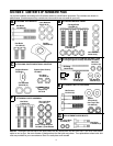
7
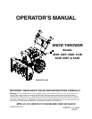
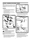
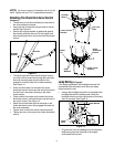
Figure 4
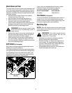
• Repeat process for the right side Traction Control.
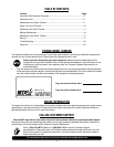
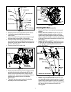
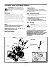
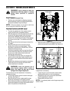
• Lay handle assembly behind snow thrower.
See Figure 5.
• Insert a hex bolt 3/4” long and lock washer through
the lower hole on the bottom of the handle.
• Hold the handle assembly up to the bottom of the
snow thrower frame and thread the hex bolt into the
lower hole in snow thrower frame. Do not tighten at
this time. See Figure 5.
• Repeat process on the other side.
Figure 5
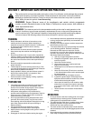
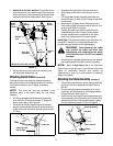
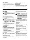
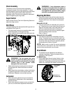
• Raise the handle assembly into the upright position
and align the top holes in the handle with the top
holes in the snow thrower frame. Attach using 2”
long hex bolts, lock washers and saddles. (Curve in
saddle must match the curve in the handle.)
See Figure 6.
• Tighten all hardware used to attach the handle
assembly to the snow thrower frame.
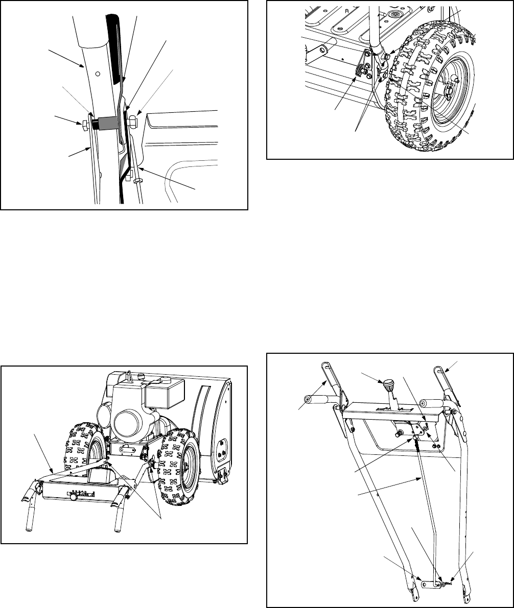
Figure 6
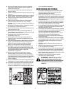
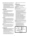
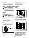
Attaching Shift Rod (Hardware D)
• Place the shift lever in the fastest forward speed
position.
• Models 602, 642, and 662: Rotate the shift arm
assembly counter clockwise, as far as it will go.
Insert the shift rod through the shift arm assembly.
When installed the shift arm assembly should point
to the right. Secure with flat washer and hairpin clip.
See Figure 7.
• Models 602, 642, and 662: Thread the ferrule up
or down the shift rod and align with the lower hole
on the shift lever assembly behind the handle
panel. See Figure 7.
Figure 7
• Models 614, 644, 664 and 6A4: Rotate the shift
arm assembly counter clockwise as far as it will go.
Insert the shift rod through the shift arm assembly.
When installed, the shift arm assembly should point
left. Secure with flat washer and hairpin clip.
See Figure 8.
Auger Control
Left Bracket
Handle Panel
Spacer
Hex Lock Nut
“Z” Fitting
Left
Handle
Hex Bolt
Hex Bolt &
Lock Washer
Handle Panel &
Handles
Cable Roller
Guide
Lock
Washers
3/4” Hex
Bolt
2” Hex Bolt
Saddle
Models 602, 642 and 662
Shift
Lever
Traction
Drive Clutch
Hairpin
Clip
Ferrule
(Bottom Hole)
Flat Washer
Shift Rod
Shift Arm
Assembly
Hairpin
Clip
Flat
Auger
Drive Clutch
Washer