


6
SECTION 3: ASSEMBLING YOUR SNOW THROWER
NOTE: References to right or left side of the snow
thrower are determined from behind the unit in the
operating position. The “operator’s position” is defined
as standing directly behind the snow thrower, facing the
handle panel.
Unpacking
• Remove staples or break glue on top flaps of the
carton. Remove any loose parts included with unit
(i.e., operator’s manual, etc.).
• Cut corners of the carton and lay ends down flat.
Remove packing material.
• Roll unit out of carton. Check carton thoroughly for
loose parts before discarding.
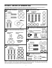
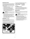
Loose Parts In Carton
Figure 1
Before Assembly
WARNING: Disconnect the spark plug
wire and ground it against the engine to
prevent unintended starting.
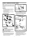
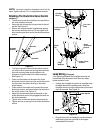
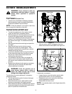
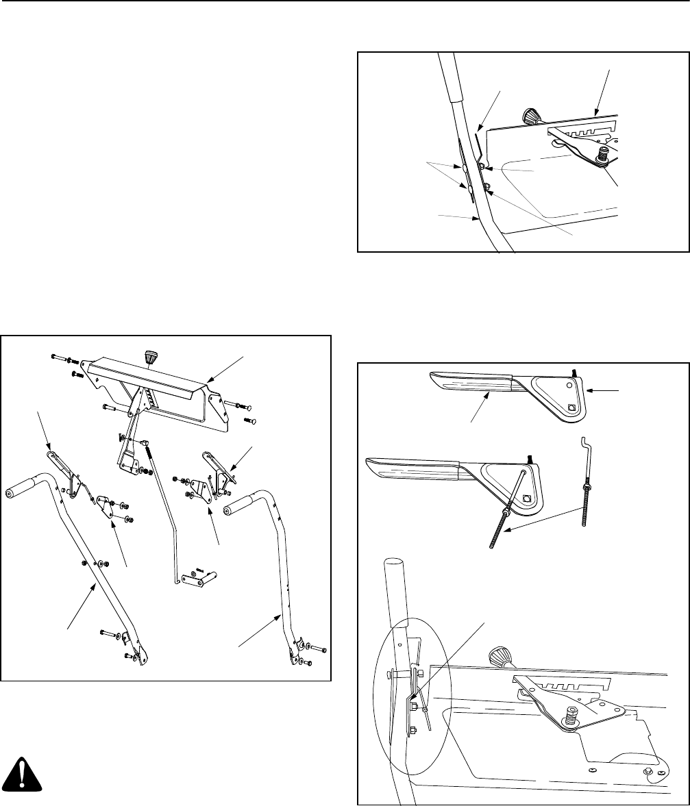
Attaching Handle Assembly (Hardware Group A,
B and E)
• Attach left handle and left clutch bracket to handle
panel with two carriage bolts, lock washers and hex
patch nuts. (Be sure the bend in the grip bracket is
towards the center of the handle panel.) Do not
tighten at this time. See Figure 2.
Figure 2
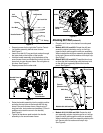
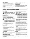
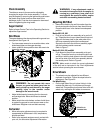
• Insert curved end of the Z fitting into the top hole in
the triangular metal tab on the auger control grip.
The triangular metal tab on the auger control grip
must face the center of the handle panel.
See Figure 3.
Figure 3
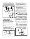
• Place the auger control on top of the left handle.
The triangular metal tab must be between the
handle and the bracket. See Figure 3.
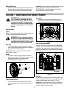
• Secure with hex bolt, spacer, and hex lock nut. Do
not overtighten this bolt as it will prevent the control
from automatically returning to their upright
position. See Figure 4.
Handle Panel
Auger Control
Traction Control
Left Handle
Right Handle
Left Clutch
Bracket
Right Clutch
Bracket
Handle Panel
Carriage
Bolts
Left Bracket
Lock Washers
Left Handle
Hex
Patch Nuts
(Curves in)
Auger Control
“Z” Fitting
Triangle
Metal Tab
Triangle
Metal Tab