


Marine Electrical Prod
ucts
PN 8100 / PN 8101 / PN 8102
Specications
Material: 0.125" 5052-H32 Aluminum Alloy
Primary Finish: Chemical Treatment per Mil Spec C-5541C
Final Panel Finish: Graphite color 2 part textured Polyurethane
Circuit Breakers: 30A Main with 30mA trip ELCI, and (if equipped),
15A single pole AC/DC Circuit Breaker
Amperage Rating: Panel is rated for 30 amps service.
Voltage Rating: Panels are rated for 120 volts AC and are so marked
in order to comply with ABYC standards
PN Inches Millimeters
Overall Dimensions: 8101/8102 5-1/4 × 7-1/2 133.4 × 190.5
8100 5-1/4 × 3-3/4 133.4 × 95.3
ApplicableStandards
• American Boat and Yacht Council (ABYC) Standards and recommended
Practices for Small Crafts sections: E-11, AC and DC Electrical Systems
on Boats.
• United States Coast Guard Code of Federal Regulations 33, Part 183,
Subpart I, Electrical Systems on Boats.
BlueSeaSystemsInc. Phone(360)738-8230
425SequoiaDrive Fax(360)734-4195
Bellingham,WA98226USA www.bluesea.com
980006510 Rev. 002
WARNING
It is not possible within the scope of these instructions to fully acquaint
the installer with all the knowledge of electrical systems that may be
necessary to correctly install this product. If the installer is not
knowledgeable in electrical systems we strongly recommend that an
electrical professional be retained to make the installation.
If either the panel front or back is to be exposed to water it must be
protected with a waterproof shield.
The panels must not be installed in explosive environments such as
gasoline engine rooms or battery compartments as the circuit breakers
are not ignition proof.
The vessel’s shore power cord must be disconnected form shoreside
power before installing this electrical panel.
If an inverter is installed on the vessel its power leads must be
disconnected at the battery before the panel installation. Be aware that
many inverters have a “sleep mode” in which their voltage potential
may not be detectable with measuring equipment.
If an AC Generator is installed aboard it must be stopped and rendered
inoperable before the panel is installed.
Verify that no other AC source is connected to the vessel’s wiring
before the panel is installed.
Installation
1. DisconnectallACandDCpower
Disconnect all AC power originating on or off the vessel. This includes
inverters, generators, shore power attachments and any other device
capable of supplying AC power to the ship’s circuits.
Disconnect the main positive DC cable from all batteries to eliminate
the possibility of a short circuit and to disable the inverter while
installing the distribution panel.
2. Selectmountinglocationandcutopening
This panel is to serve as your main shore power disconnect circuit
breaker. Select a location which is not more than 10 feet from the
shore power inlet or the electrical attachment point of a permanently
installed shore power cord as measured along the conductors of the
feed wires. If it is more than 10 feet additional fuses or circuit breakers
must be installed within 10 feet of the shore power inlet.
Select a mounting location which is protected from water on the panel
frontandbackandisnotinanareawhereammablevaporsfrom
propane, gasoline or lead acid batteries accumulate. The circuit
breakers used in this marine electrical panel are not ignition protected
and may ignite such vapors.
Using the panel template provided, make a cut out in the mounting
surface where the distribution panel is to be mounted. Do not yet
fasten the panel to the mounting surface.
3. Installbranchcircuitwires
Determine the proper wire size for each branch circuit using the wire
sizing chart . Verify that the standard 15 amp circuit breakers installed
in the panel are correct for each branch circuit. Remove and replace
any that are incorrectly sized. The circuit breaker must have a rating
less than the allowable amperage of the wire, yet greater than the
circuit’s continuous current.
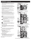
120V AC ELCI Main panels
Connect each branch circuit hot (black) to the appropriate load terminal.
Connect each branch circuit neutral (white) to one of the screws on the
neutral bus. Connect each branch safety ground wire (green) to one of
the screws of the safety ground bus.
Do not confuse the neutral current carrying wires (sometimes called
ground) with the green normally non-current carrying wires (sometimes
called grounding). These two wires must be connected only at the
source of power, nowhere else.
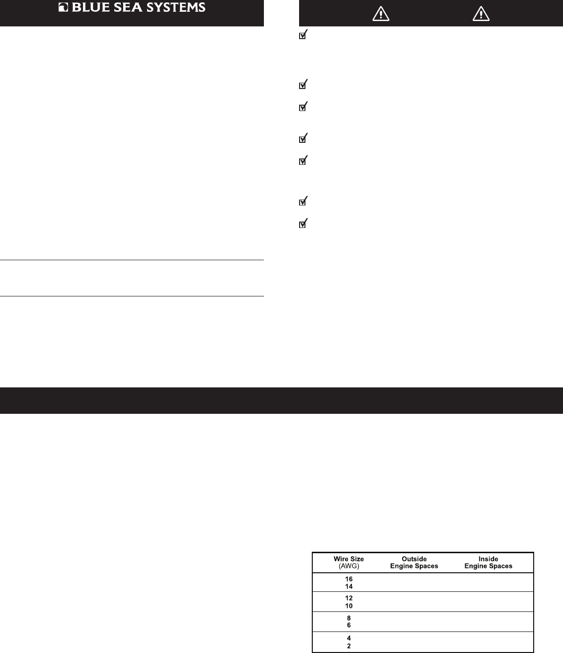
Wiresizingchart
Use the wire sizing chart below to determine the minimum
branch circuit wire sizes.
ABYC E-11 Table VI-B 105˚ C ( 221˚ F) Wire
Note: This chart assumes wire with 105° C (221° F) insulation
rating and no more than 3 conductors are bundled.
Not suitable for sizing flexible shore power cords.
Blue Sea Systems recommends that the feeder wires from the
power inlet to the panel should be 10 AWG for 30A systems and
6 AWG for 50A systems.
17.5
24.5
31.5
42.0
56
84
112
126
11.9
20.8
26.8
35.7
47.6
71.4
95.2
107.1
GUARANTEE:BlueSeaSystemsstandsbehinditsproductsforas
longasyouownthem.Finddetailedinformationat
www.bluesea.com/about.Forcustomerservice,call800-222-7617.