Audio-Technica U.S., Inc., 1221 Commerce Drive, Stow, Ohio 44224
Audio-Technica Limited, Old Lane, Leeds LS11 8AG England
©2010 Audio-Technica U.S., Inc. audio-technica.com 0001-0096-00
wireless microphones & system accessories
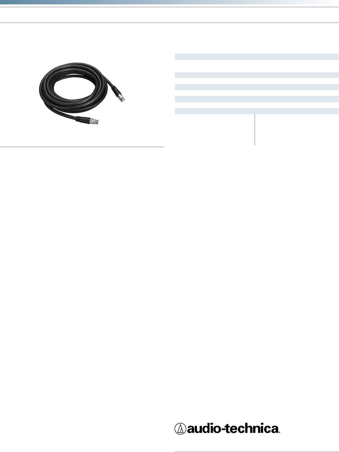
AC25, AC50, AC100
RF Antenna Cables (25' RG8, 50' RG8, 100' RG8)
Features
• RG8-type exible coaxial cable
• 10 AWG stranded center conductor
• Bonded foil shield with tinned copper braid overlay
• Heavy-duty molded BNC connectors
• Ideal for portable or xed-installation applications
Description
The AC25, AC50 and AC100 are pre-made antenna cables designed for
remote antenna-to-receiver runs. The cables are constructed of a exible
low loss RG8-type coaxial with molded BNC-type connectors.
Architect’s and Engineer’s Specications
The antenna cable shall consist of a pre-manufactured and tested (Note
to specier: insert required length 25', 50', 100') length of RG8/U-type
exible coaxial cable with molded heavy-duty BNC-type connectors at
each end suitable for indoor and outdoor applications. It shall consist of
10 AWG stranded bare copper center conductors with 7x19 strands. The
center conductors shall have foam-polyethylene insulation surrounded
by a bonded aluminum foil-polyester tape and aluminum foil along with
a +90% tinned copper braid shield. The exible outer jacket shall be
constructed of PVC—Polyvinyl Chloride material with a nominal OD of
.405". The cable shall have an impedance of 50 ohms and a nominal
capacitance of 24.6 pF/ft. Insertion loss at 400 MHz shall not exceed
2.6 dB. At each end of the cable shall be tted a standard BNC-type
locking connector. The connectors shall be integrally molded onto the
cable and incorporate a built-in strain relief.
The antenna cable assembly shall be an Audio-Technica (Note to
Specier: choose appropriate length), or equivalent.
AC25—25'
AC50—50'
AC100—100'
Specications
RG8U
100% bonded aluminum foil with tinned
copper braid overlay
50 ohms
24.5 pF/ft
2.6 dB (per 100' @ 400 MHz)
Molded-on BNC Female
Foam-polyethylene
PVC
0.405"
Cable type
Shield
Impedance
Nominal capacitance
Insertion loss
Connectors
Dielectric
Jacket
Nominal OD
* Within specied bandwidth
In the interest of standards development, A.T.U.S.
offers full details on its test methods to other industry
professionals on request.
Specications are subject to change without notice.
