1
9
LITERATURE NUMBER
MPD 85810
TELESCOPING
STABILIZER
SAFETY ALERT SYMBOLS
Safety Symbols alert you to potential personal safety hazards. Obey all safety
messages following these symbols.
ƽ WARNING ƽ CAUTION
avoid possible avoid possible
injury or death injury and/or property damage
For your safety read all instructions before operating landing legs.
Installer: Provide these instructions to the consumer.
Consumer: Keep documents for future reference.
DO NOT EXCEED CAPACITY
STABILIZER 2˝ SQUARE 2.5˝ SQUARE
MAXIMUM VERTICAL LOAD
3,000 LB. 6,000 LB.
ƽ WARNING
TRAILER CAN MOVE OR COLLAPSE
• Never exceed the rated capacity.
• STABILIZERS ARE NOT DESIGNED TO BE USED AS TRAILER JACKS. Do not use
the stabilizer to lift or support the trailer during tire changes, axle
work or trailer servicing (the trailer weight will exceed the capacity
of the stabilizer). The stabilizer is designed to stabilize a portion of
the trailer’s weight. Support the front end of the trailer with structur-
al stands rated for the GVWR of the trailer.
• The pin between the housing and drop tube should be the same
diameter as the adjustment hole in the drop tube. Otherwise prema-
ture wear on drop tube and housing can occur.
INSTALLATION
ƽ
CAUTION
HAZARDOUS FUMES
• Adequate ventilation must be provided when welding.
WELDING INSTRUCTIONS
• M.I.G. OR STICK - Attach with 3/16˝ fillet weld minimum.
• M.I.G. WELDING - Use A.W.S. ER 70S-3 or 6 wire or equivalent with a
diameter of .035 - .045. The recommended shielding gas mixture is
75% - 95% Argon & 25% - 5% CO
2
.
• STICK WELDING - Use E6011 A.W.S. welding rod or equivalent.
Recommended machine settings for specific electrode diameters are
as follows: 1/8˝ electrode set power between 115-130 Amps DC or
5/32” electrode set power between 140-160 Amps DC.
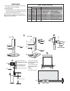
1. Weld two sides of housing to structural attachment point on trailer
surface (FIG 3-A, 4-A & 4-B). Use a minimum of 4˝ of 3/16˝ fillet lin-
ear weld total on each side, stich or continuous (FIG 4-A & B). See
welding instructions. When locating housing on trailer make sure
access for lock pin is available for easy adjustment.
2. Assemble foot pad (
FIG 1-D) to drop tube (FIG 1-B) with bridge pin
clip (
FIG 1-C) and clevis pin (FIG 1-E) for 2.5˝ square stabilizer.
3. Assemble drop tube (
FIG
1-B) to 2.5˝ square housing (
FIG 1-A) in a
fully retracted position using lock pin (FIG 1-G). For 2˝ square, assemble
drop tube to housing with the ball detent pin (
FIG 1-F). Mount footpad
with its length running from front to rear of the trailer.
NOTE: Optional spring-loaded pull pins (FIG 2-A Pull Pin or FIG 2-B on
the 2.5˝ square stabilizer “SNAPS
TM
”) are available to replace FIG 1-
G or F respectively. There must be a half-hole at the bottom of
the housing in order to use the pull pin. If using a pull-pin,
assemble it to the housing per its instruction manual.
OPERATION
ƽ WARNING
MOVING PARTS CAN CRUSH OR CUT OR PINCH POINT
• Keep hands and clothing away from moving parts.
ƽ WARNING
TRAILER CAN MOVE OR COLLAPSE
• Never exceed rated capacity of stabilizer.
• STABILIZERS ARE NOT DESIGNED TO BE USED AS TRAILER JACKS. Do not use the
stabilizer to lift or support the trailer during tire changes, axle work
or trailer servicing (the trailer weight will exceed the capacity of the
stabilizer). The stabilizer is designed to stabilize a portion of the trail-
er’s weight. Support the front end of the trailer with structural stands
rated for the GVWR of the trailer.
• Chock both sides of trailer wheels before operating stabilizer.
• All legs must touch the ground or the surface at the same time.
• Retract stabilizer completely before towing trailer.
ƽ CAUTION
SECURE TRAILER BEFORE TRAVELING
• Before retracting, ensure there is no load on the stabilizer. Securely
latch hitch before retracting stabilizer.
• Lock pin spring clip must be positioned around stabilizer and
secured over end of pin on opposite side of housing tube. This pre-
vents pin from coming out during travel (
FIG 1-G).
• FOR 2.0˝ STABILIZER insure the ball detent pin is fully extended
through the leg (
FIG 1-F).
TO EXTEND THE STABILIZER - Remove the pin in the drop tube or, if
you have a pull pin that doesn’t remove, pull the handle pin so the pin
is disengaged. Let the drop tube fall to the ground and re-pin in the
nearest adjustment hole.
TO RETRACT STABILIZER - Make sure there is no load on the stabiliz-
er. Remove pin or disengage the pull pin and raise the drop tube, re-
pinning it in the highest position. Fully retract the legs so that the foot
pad is higher than the lowest point of the trailer, to prevent dragging
while going over a curb.
Before towing, check for maximum clearance between ground and bot-
tom of stabilizer.
ENGLISH •Installation •Operation •Maintenance
Effective 11/21/07