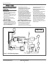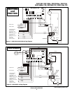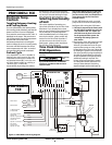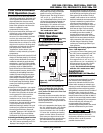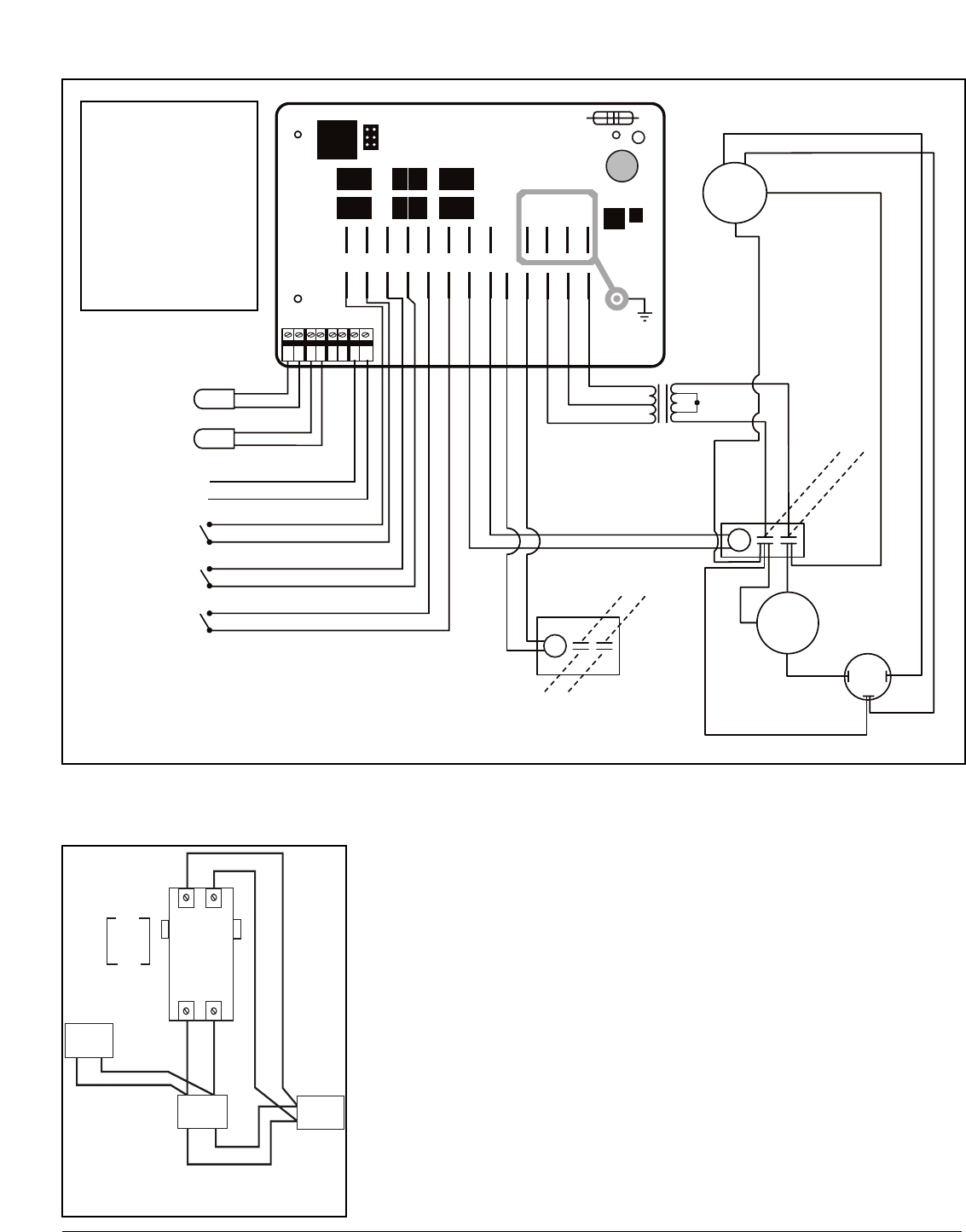
Figure 7 - PRO1100e TCE & PRO1300 TCE wiring diagram
Water Sensor
Defrost Sensor
High Pressure Switch
Closed = OK
Opened = High Pressure
Low Pressure Switch
Closed = OK
Opened = Low Pressure
Flow Switch
Closed = Flow
Opened = No Flow
MY-TECH PH-111A
Brown
Brown & White
SPR1
SPR2
REVR
JANDY
HP
LP FLO
COMP
PUMP
12 ~8 ~12
AC F1 F2 F3
WS
DS
AS
P/S
Black
Black
Blue
Orange
Blue
Orange
Blue
Gray
12 VAC
Blue
Red
Blue
12 / 24 VAC Transformer
Black
Yellow
Yellow
24
Vac
COMPRESSOR
R
S
C
24 VAC
Compressor
Contactor Coil
Run Cap
L1
L2
Black
Black
Yellow
Black
Black
Red
H
C
F
Red
Blue
FAN
Black
Black
White
24 VAC
pool pump
contactor coil
L4
Pool Pump
L3
PRO1300, PRO1100e, PRO1300h/c, PRO1100,
PRO1300h/c TCE, PRO1300 TCE, PRO1100e TCE
Phone: (877)-278-2797
7
www.aquaprosystems.com
To Remote System
(If Applicable)
•
This unit is prepared at the factory with
the “FIL” mode set to the “off” position.
You will need to set the heat pump’s
hours of run time in the “FIL” mode to
“2” hours. See “activating and setting
system run time” below to set the run
time. Leave your time clock set to the
desired pump and filter operation time.
This will enable the heat pump and filter
system to run the desired hours of the
day and also provide the benefit of
checking if heat is needed every 4 hours.
It will do this by running the pump and
filter system for 15 minutes. If heat is
needed, it will continue to run until the
pool has reached the set temperature. If
no heat is needed, the system will turn
off and continue checking for heat every
4 hours. This provides a couple of added
benefits. Pools will lose most of their
heat at night if left uncovered, however,
since the unit is checking for and adding
heat when needed, it prevents long
recovery times when compared to non-
TCO units. The other benefit is that some
states and electric utility companies offer
a discount for off-peak usage of
electricity. Please contact your electricity
provider if you have questions.
Activating and Setting System Run
Time – TCO Operation
•
To set the run time of the system,
push the “SET” button repeatedly
until “FIL” displays. Then using the
“up” and “down” arrows, set the
hours to “2”. The range of hours is
“off” to 2, 3, 4,… up to 23 hours to
“on”. By selecting “2” the heat pump
will run every 4 hours for 20 minutes,
checking if heat is needed. The unit
leaves the factory with the “FIL”
mode set to “OFF”.
Time Clock Override
(TCO) Operation (cont.)
BREAKER
TIME
CLOCK
FILTER
PUMP
CONTACTOR
FOR THE
TIME
CLOCK
OVERRIDE
INSIDE
HEAT
PUMP
T2 T1
L3 L4
INSIDE
HEAT
PUMP
CONTACTOR
FOR THE
TIME CLOCK
OVERRIDE
TIME
CLOCK
FILTER
PUMP
BREAKER
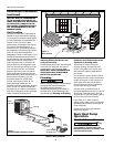
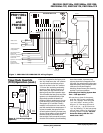
Figure 8 - TCO wiring diagram
(optional)
PRO1100e
TCE
and
PRO1300
TCE


