


The pump mount must be located away
from corrosive or fl ammable chemicals.
Do not connect the pump to a municipal
water system. The pump is only designed for
pool or spa installation. The pump must be
installed with at a minimum of 2 main drains
equipped with certifi ed anti-entrapment cov-
ers that comply with ASME/ANSI A119.19.8
standard (see Figure 2). All air must be re-
moved from piping system before operating
or testing equipment (see fi lter manual).
THREADED CONNECTIONS
Use only Tefl on
®
tape or equivalent on
threaded plumbing connections. Other pipe
compounds may damage threads. Do not
use silicone or petroleum based compounds.
PUMP PLUMBING
Suction pipe should be as large as or
larger than discharge pipe. Avoid us-
ing a suction pipe smaller than pump
connection. The pump is designed to
accept either 2 or 3 inch suction piping.
Larger diameter pipes reduce noise and
improve performance.
1. Keep the piping as straight and short
as possible, and of suitable size.
2. Avoid connecting an elbow directly
into the pump inlet. A length of
straight pipe will allow proper entry
of the water to the pump.
3. Slope horizontal runs upward to the
pump to prevent trapping air.
4. Use independent piping supports to
reduce strain on the pump.
5. Keep as much of the suction line as
possible below the water level to
reduce priming time.
6. Install valves and unions in the pump
suction and return lines to facilitate
servicing. Valves are also essential for
pump maintenance if the system is
installed below pool water level.
7. Keep all valves fully open during
operation. Partially closed valves waste
energy!
Use Tefl on tape for
making threaded
connections to the pump. Do not use
pipe dope.
TEFLON TAPING INSTRUCTIONS
Use only new or clean PVC pipe fi ttings.
Wrap male pipe threads with one to
two layers of Tefl on tape. Cover entire
threaded portion. Do not over tighten.
If leaks occur, remove pipe, clean off old
tape, rewrap with one to two additional
layers of tape and remake the connection.
Internal - 2 in. NPT
are available for direct
connection to pipe. The suction line is
also designed to accept 3 in. NPT external
threaded connection. For best results use
the larger diameter suction line.
FITTINGS
Fittings restrict fl ow; for best effi ciency
use fewest possible fi ttings. Avoid fi ttings
which could cause an air trap. Pool fi ttings
must conform to International Associa-
tion of Plumbing and Mechanical Offi cials
(IAPMO) standards. Use only non-entrap-
ping suction fi tting or double suction.
PRIOR TO PRESSURE TESTING
• Securely tighten knobs, drain fi ttings,
lid, and system accessories
• Air may collect at the highest point in
the plumbing system. Normally an air
purge valve is provided with the pool
fi lter. Consult pool fi lter instruction
manual for air purging instructions.
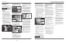
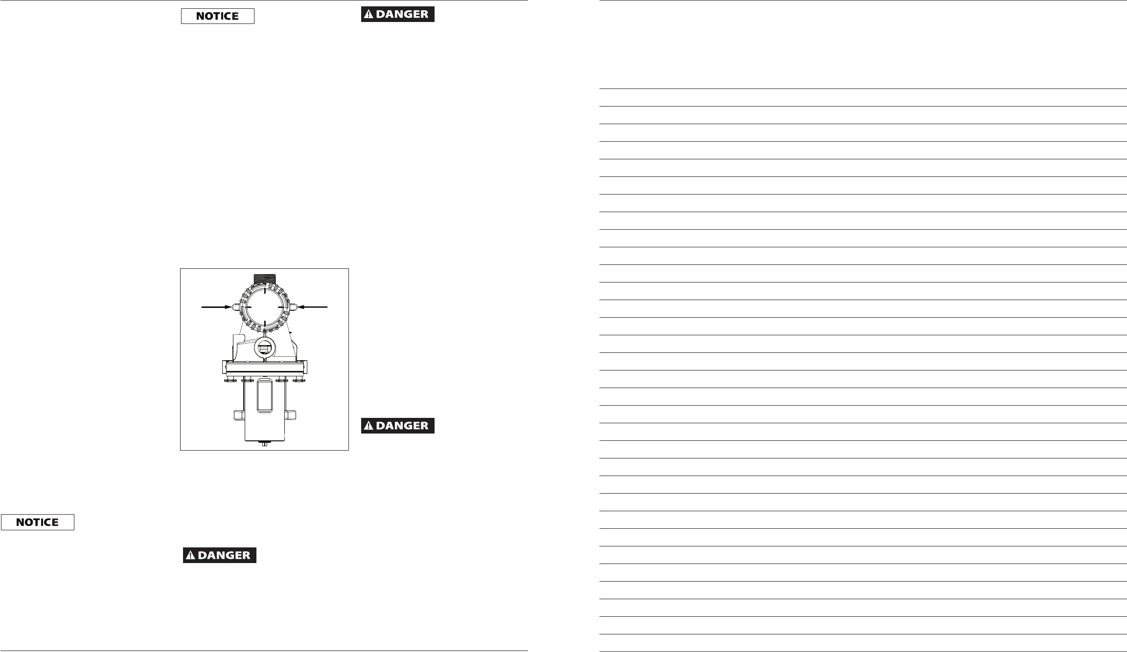
• Basket lid must be rotated and locked
into position as indicated in Figure 3.
• Test system at a water pressure of 25
psi or less
• Water Temperature for test must be
less than 100° F
• After 24 hours visually check system
for leaks.
POOL PUMP SUCTION REQUIREMENTS
Pump suction is
hazardous and can trap,
drown or disembowel bathers. Do not use or
operate swimming pools or spas if a suction
outlet cover is missing, broken, or loose.
Follow the guidelines below for a pump
installation which minimizes risk to users of
pools and spas.
Ground the motor
before connecting
to electrical power supply. Failure to
ground the motor may cause severe or
fatal electrical shock hazard.
ENTRAPMENT PROTECTION
The pump suction must be designed to
eliminate the possibility of suction entrap-
ment or hair entrapment/entanglement.
SUCTION COVERS
All suction inlet covers must be maintained
and replaced if cracked, broken, or missing.
See Figure 2 for outlet cover certifi cation
requirements.
TESTING AND CERTIFICATION
All suction inlet covers must comply with
ASME/ANSI A112.19.8 specifi cations for
suction fi ttings for use in swimming pools,
spas and whirlpool bathtub applications. The
product must be tested for compliance with
the standards and the certifi cation must be
included with the components.
Single or Multiple Pump Circulation Sys-
tems must be provided with a minimum of
2 (two) suction inlets of the approved type.
Do not install multiple pumps in one
hydraulic circuit. The pump is not designed
to accept output fl ow from another pump.
Do not allow water to back fl ow through
the pump. Water fl owing in the discharge
and out the suction during an upset
condition can cause the motor to rotate
backwards. Never attempt to start pump if
shaft is rotating due to a hydraulic turbine
action, this could cause pump to operate in
reverse and damage internal components.
Any pool or spa
should immediately
be closed if the cover or grate is
damaged or missing.
OUTLETS PER PUMP
Provide at least two hydraulically balanced
main drains, with covers for each swimming
pool pump suction line. The centers of the
main drains suction fi tting must be at least
three feet apart (see Figure 2). The system
must be built so that it cannot operate with
the pump drawing water from only one
main drain. Two main drains must be con-
nected to the pump whenever it is running.
If two main drains run into a single suction
line, the single suction line can be equipped
with a single valve that shuts off both main
drains from the pump. A valve in each
suction line is not allowed.
Installation (Cont.)
4
www.aquaprosystems.com
Owner’s Manual
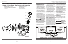
Figure 3 - Clamp rings
Notas
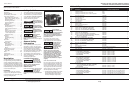
APB075PRO, APB100PRO, APB150PRO, APB200PRO, APB300PRO,
APB100UPRO, APB150UPRO, APB200UPRO and APB250UPRO
21 Sp